

Tips & Useful Information
CV and CC on a Laboratory Power Supply: Why the Voltage Drops Under Load
The lab power supply is set to 24 V, but only 12 V is present at the output under load. At the same time, the device displays 2 A and the status "CC." Before assuming that the power supply is too weak or defective, it’s worth checking the set current limit. In this situation, the power supply is regulating exactly as intended.
CV and CC stand for constant voltage and constant current. Which parameter the power supply is currently regulating depends on the setpoints and the connected load. This not only explains the lower voltage but also helps with the next decision: Is the current limit appropriate for the task, or is the problem caused by the connected circuit?
Two setpoints, one common operating point
In constant-voltage mode—CV for short—the power supply maintains the selected output voltage within its specified limits. The current is determined by the load. Therefore, a current limit set to 2 A does not mean that 2 A flows through every connected module. If a module requires only 0.4 A at the set voltage, the power supply delivers that current.
If the load were to draw more than the set limit at this voltage, a CV/CC power supply would switch to constant-current mode. It adjusts the output voltage so that the specified current is maintained. CC stands for Constant Current. The set voltage remains the upper limit: If the load requires a higher voltage to achieve the desired current, the source remains at its voltage limit and does not reach the current setpoint.
With a power supply that features automatic CV/CC switching, you do not need to trigger this switch manually. You set the voltage and current limits; the load helps determine which control mode results from these settings.
A sample calculation using 24 V and 2 A
Let’s consider an ideal, purely resistive load. The power supply is set to 24 V, and the current limit is set to 2 A. For the calculation, we will assume steady-state conditions, ignoring line losses and tolerances. The values are arbitrary and do not correspond to any measured setup.
| Load resistance | Current at a constant 24 V | Calculated operating point with a 2-A limit | Steady State |
|---|---|---|---|
| 24 Ω | 1 A | 24 V / 1 A | CV |
| 12 Ω | 2 A | 24 V / 2 A | CV/CC Transition |
| 6 Ω | 4 A | 12 V / 2 A | CC |
At 24 Ω, the current is 1 A according to I = U / R. The current limit has not yet been triggered. If the resistance drops to 6 Ω, however, 4 A would be required at 24 V. The set limit allows only 2 A. It follows that the load voltage is U = I × R = 2 A × 6 Ω = 12 V.
The lower voltage here is the result of current regulation. If the 6-Ω resistance remained unchanged, 24 V would actually require 4 A and 96 W. Increasing the current limit would therefore change the operating point. Whether this is advisable depends on the current that the load, wiring, and connections can handle, as well as the objective of the experiment.
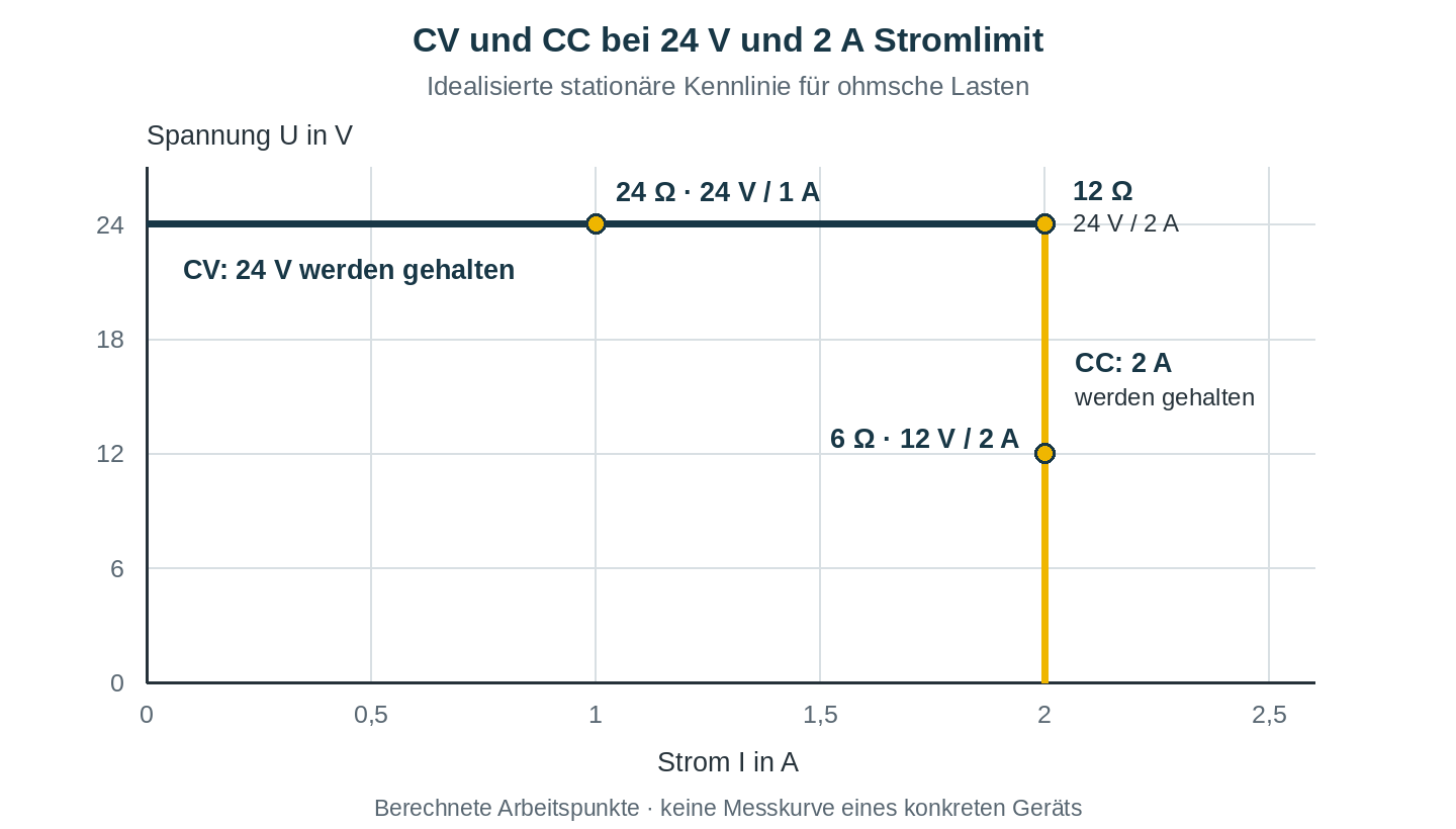
The idealized characteristic curve illustrates this transition. It shows the relationship between load and setpoints in steady state. It does not indicate how a real device would respond to a rapid load change.
Compare the setpoint and measured value side by side
When troubleshooting, it helps to view the set values alongside the actual measured output values. The DP-H Series’ numerical display provides separate set and actual values specifically for this purpose. On the DP30-30H from DSC-Electronics Germany, this allows you to see which voltage you have set and which current limit is configured, while reading the actual voltage and current at the output.
In our example, this means that the 24 V setpoint is different from the 12 V output in CC mode. Displaying these values separately makes this distinction clear. Together with the active control state, this makes it possible to determine whether the device is maintaining the desired voltage or limiting the set current.
The DP30-30H offers 0–30 V, 0–30 A, and 900 W of rated power; the calculated operating points fall within these rated limits. Its automatic CV/CC transition handles the switch between voltage and current regulation based on the load. This means you can select a limit that is appropriate for the device under test, even if the power supply could deliver significantly more current. Its maximum current is not a specification for the connected setup.
CC and overcurrent protection serve different purposes
CC can be a desired operating condition, for example, when a suitable test object needs to be supplied with a constant current. However, a module that requires a fixed supply voltage may not be able to achieve this operating condition as long as the power supply limits the current.
An overcurrent protection function, often referred to as OCP, can shut off the output when its trigger condition is met, rather than continuing to supply power in CC mode. In the DP-H series, OCP and the overvoltage protection function (OVP) are each set and enabled separately. Both are disabled by default. If one of these shutdown functions is to be added to the system, the appropriate threshold value and activation must be configured together; the current setpoint alone does not enable OCP.
For short current pulses, dynamic behavior is also important. A control system does not respond instantly, and charged capacitors can release energy. The set current limit therefore does not guarantee that every pulse—no matter how short—will remain exactly below that limit. For sensitive circuits, what matters is the load they can withstand even during power-up or in the event of a fault.
Why CC Sometimes Appears Only When the Device Is Turned On
A circuit may require little power after startup but still briefly reach the current limit when powered on. One possible reason is its input capacitance, which must first be charged. If the voltage remains too low during this process, the device under test may not yet reach its intended operating state.
Therefore, observe when CC appears: immediately after power-up, only during certain load changes, or continuously. This information is often more helpful than a single current reading. Together with the permissible inrush current and the module’s startup conditions, it indicates whether the limit is appropriate for the application. A higher value may be considered if the application’s requirements and the system’s capacity allow it.
Limiting the voltage dip
For the next step in the test, it is crucial to determine where the voltage is missing and what the power supply indicates:
| Observation | The most sensible next step in the testing process |
|---|---|
| CC active, measured current near the set limit | Compare the load's power requirements, the wiring, and both setpoints. Determine why the load is reaching the limit. |
| CV active; lower voltage across the test specimen than at the output | Check for voltage drops across wires and contacts. Distinguish between the output voltage and the load voltage at the respective measurement points. |
| Output disabled or protection message present | Check the displayed cause of the trip and its limit values. Correct the cause before re-enabling the output. |
If this requires reconnecting wires, disconnect the power sources first and check for any residual voltage. The "OFF" position does not provide electrical isolation; even connected batteries or capacitors may continue to supply power.
If you’re still unsure about which output range to choose, our article “From Operating Point to the Right Lab Power Supply” can help . If you have questions about selecting a device or about a planned test setup, you can reach us at service@dsc-electronics.de. It’s helpful to provide the intended voltage and current values, as well as a brief description of when the transition to CC occurs.
