

Tips & Useful Information
Which laboratory power supply is right for you? From operating point to the right model
Imagine a development workstation where, today, an assembly is being tested at 24 V and 35 A; tomorrow, a second one at 48 V and 20 A; and later, a third one at 72 V and 15 A. Which lab power supply would you choose for this? If you simply enter the highest voltage and current into your search, you’ll quickly end up with a unit that’s larger than these three tasks require.
When making a selection, it is therefore worth taking a look at the individual operating points: What voltage and current are actually required at the same time? This deliberately hypothetical test setup demonstrates how this question can be used to make a sensible preliminary selection. The values are arbitrary; they do not represent actual measurements or a customer project.
Three operating points instead of two maximum values
The three assemblies are powered sequentially. The DC power required by each can be calculated using the formula P = U × I:
| Test | Required Voltage | Required current | Calculated output power |
|---|---|---|---|
| A | 24 V | 35 A | 840 W |
| B | 48 V | 20 A | 960 W |
| C | 72 V | 15 A | 1.080 W |
The maximum voltage is 72 V, and the maximum current is 35 A. If the power supply were to provide both values simultaneously, it would have to deliver 2,520 W. However, none of the three tests requires this maximum output. The maximum output power actually required is 1,080 W.
Here, it’s worth comparing this to an autoranging power supply. It combines a wide voltage and current range with an additional power limit. One example from the Laborance lineup is the DP85-40-1500HA from DSC-Electronics Germany: It offers 0–85 V and 0–40 A at a maximum of 1.5 kW. All three operating points fall within these rated limits. This puts it on the shortlist for the test bench; we’ll take a closer look at its load behavior and features next.
The power limit remains the decisive factor here. At 72 V, 1,500 W divided by 72 V yields a calculated current limit of approximately 20.83 A. At 40 A, the corresponding voltage limit is 37.5 V. The combination of 85 V and 40 A is therefore not possible within the 1.5 kW power limit. Keysight also explains how such an output characteristic curve is generated, using autoranging power supplies as an example.
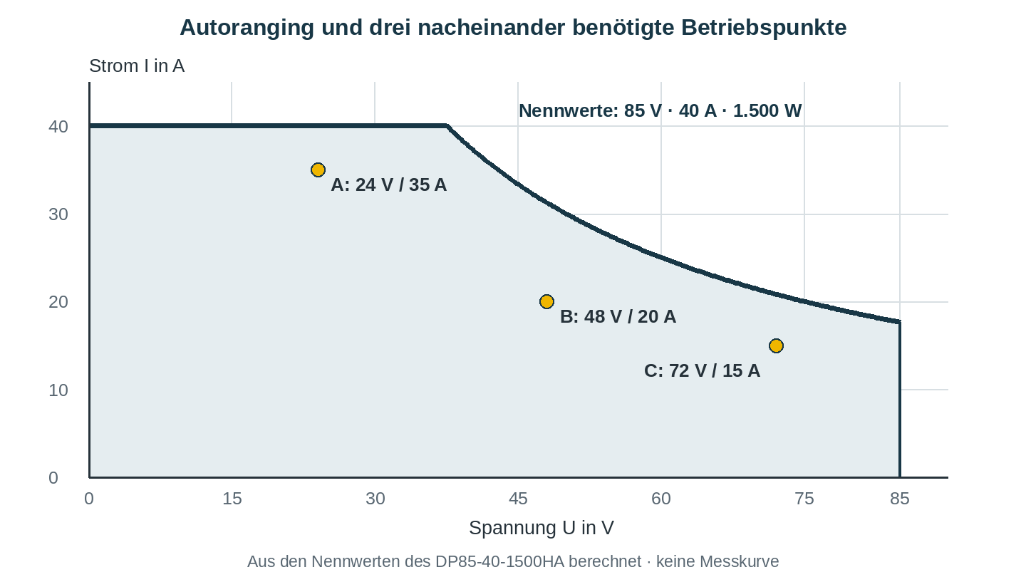
This approach is also helpful for other tasks: Record the corresponding voltage and current values for rated operation, range limits, and different loads. If multiple modules are to be powered simultaneously, the number of independently controllable outputs and their electrical relationship to one another should also be considered in the selection process.
What happens when the device is turned on and under load?
The operating points describe the power requirements, but not the entire test procedure. The power source may need to charge an input capacitance at startup or briefly supply a higher current than during subsequent operation. Whether this load lasts a few seconds, recurs regularly, or persists for hours can be decisive for suitability. Duration and repetition are therefore just as much a part of the requirements as the specified environmental and cooling conditions. A general power reserve does not answer these questions.
The interaction between voltage and current regulation also warrants attention. In constant-voltage (CV) mode, the power supply maintains the set voltage; the load determines the current flow within the set limit. If the load requires more current than the limit allows, a power supply designed for this purpose switches to constant-current (CC) mode and reduces the voltage. This may be exactly what is desired during a current test. If, on the other hand, a module is to start up with an unchanged voltage, it must be verified whether the intended startup procedure works with the selected current limit.
Therefore, in addition to the rated values, you should also inquire about the dynamic behavior: How quickly does the output recover after a load change, and how does it respond to a new setpoint? These are two different parameters. Which one is important for your application will depend on the test procedure.
What level of accuracy is required for the test?
A high-resolution display is convenient when setting values. However, this alone does not indicate whether the displayed or set voltage meets the requirements. Setting resolution, setting accuracy, and display accuracy describe different characteristics. When percentages are involved, it is also important to consider what they refer to: The same numerical value means something different when based on the measured value than when based on the full measurement range.
The starting point should be the permissible deviation for your test. This determines the requirements for the accuracy and stability of the source and, if necessary, for additional measurement equipment. When comparing residual ripple, units and measurement conditions are important factors: RMS and peak-to-peak values cannot be easily converted into one another without knowledge of the signal waveform. Tektronix provides a more detailed explanation in its notes on power supply specifications.
The equipment must be suitable for the workplace
Once the electrical preselection has been made, the operation and integration into the test station can be determined. Two devices with similar power ratings can have significantly different areas of focus here. The DP60-20P-S provides 0–60 V and 0–20 A at 1.2 kW. It comes standard with RS232 and RS485 with Modbus RTU, as well as an interlock loop. LAN and analog I/O are available as options; the analog package replaces RS232. Remote measurement and Master/slave parallel operation are not included with this specific model.
In contrast, the DP85-40-1500HA offers RS232 with SCPI, RS485 with Modbus RTU, test sequences stored in the device, and remote measurement to compensate for line losses of up to 2 V. Its external program trigger controls the sequence and is not a safety interlock. For the planned automation, it is therefore worth taking a close look at the functions and protocols: A connector alone does not indicate how the controller communicates or what safety functions are available.
At high currents, the path from the output to the device under test must also be taken into account. Voltage drops occur across wires and contacts. Remote measurement records the voltage at the load and can compensate for such losses within the specified compensation limit. However, it is no substitute for wires with sufficient current-carrying capacity or properly designed connections.
If the device under test can feed energy back, an additional requirement applies: The design must account for reverse current, reverse voltage, and stored energy. Existing reverse-current protection does not turn a source into a universally usable electronic load and does not establish that it can absorb energy regeneratively.
Compare items specifically based on a clear requirement
An operating point table like the one in the example—supplemented with load duration, turn-on behavior, and permissible deviations—often provides a good basis for technical preselection. Other factors to consider include the required outputs and interfaces, the available space, and the power connection. Planned expansions should be as specific as possible so that it is possible to assess which reserves and functions will be useful later on.
In the Laborance catalog for DC laboratory power supplies, you can narrow down your selection by output range and features. The technical specifications and the corresponding operating instructions for the selected model will then apply. If you would like to discuss your operating points and test procedure with us, please email service@dsc-electronics.de. We will assist you in selecting the model and the necessary features.
