
Compact designs for rack-mounted and desktop use
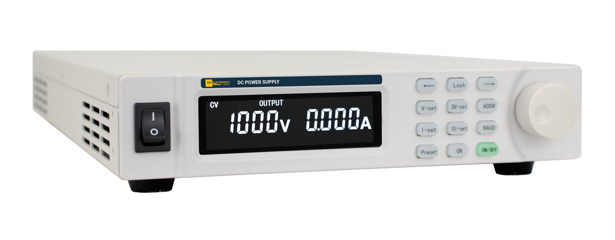
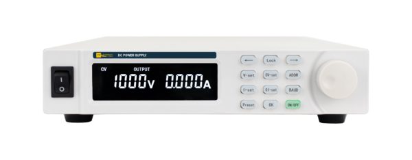
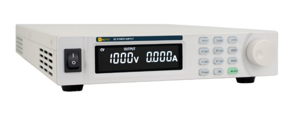
Illustration of a DP30-60M power supply unit. The dimensions of the selected model apply for installation.

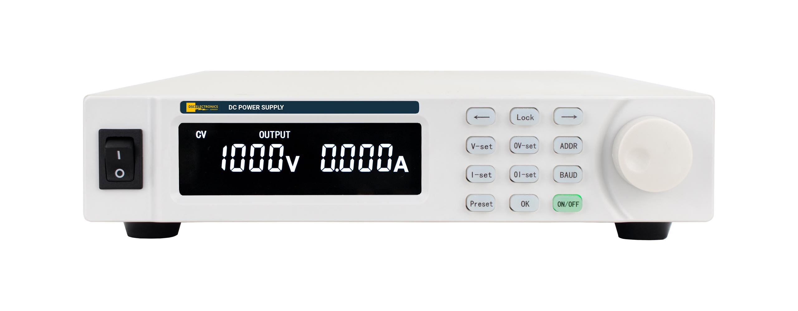
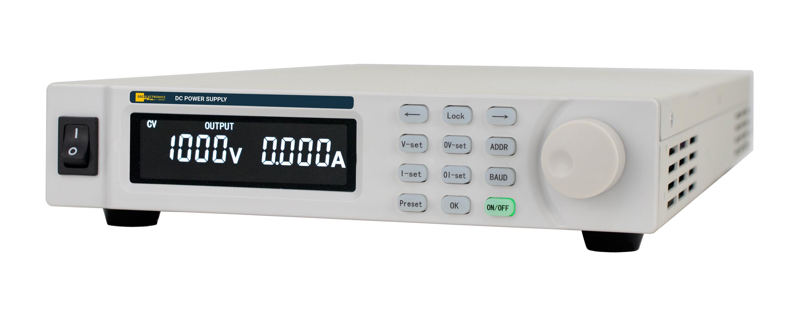
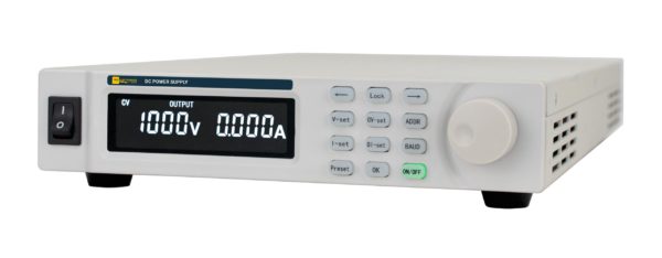
Flexible DC power supply for laboratories, industrial applications, and existing test benches: The DP-M series from DSC-Electronics Germany combines digital CC/CV control with RS232/RS485 and remote measurement up to 2 V. The optional analog package includes voltage and current control as well as both actual value outputs with a common signal type: 0 … 5V, 0 … 10V, or 4 … 20mA. The A1 interlock loop is included in the package. The analog functions cannot be selected individually. LAN and modules AP5 through AP9 are also available as options.
Note on Product Status: The DP-M series is being phased out and will be replaced by the DP-P and DP-PH series. Regular sales will continue through 2027. After that, DP-M series devices will only be available to existing customers with DP-M systems for expansion or supplementation.
High-performance DC power supply, flexibly integrated into your process: The DP-M Series combines digital CC/CV control with versatile interfaces and a variety of enclosure formats. For laboratory applications, industrial test benches, and the expansion of existing systems, it offers a proven platform with convenient front-panel operation and extensive remote control capabilities.
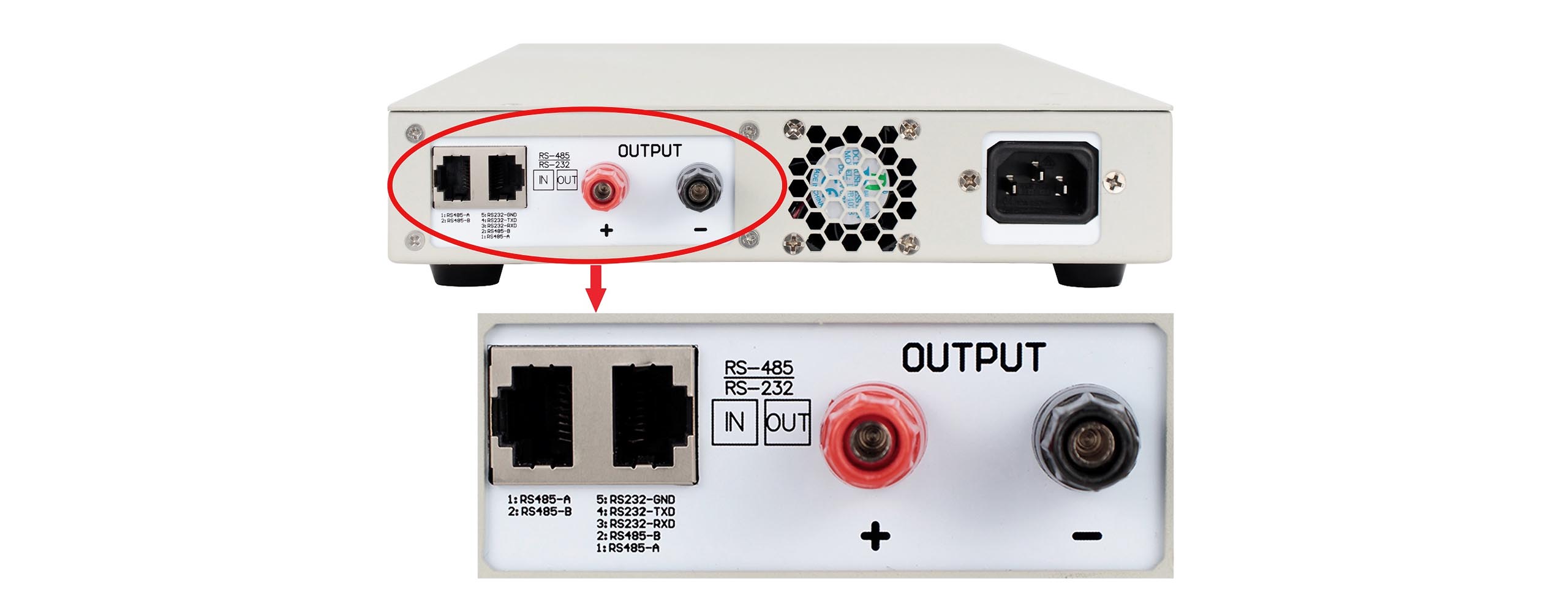
RS232 and RS485 with Modbus RTU are standard features. Optional LAN and analog inputs and outputs allow you to tailor the connection to your infrastructure. The automatic switching between constant voltage and constant current, as well as remote measurement, support controlled power delivery to varying loads.
| Connectivity | RS232 and RS485 with Modbus RTU as standard. Optional LAN and analog I/O for 0 … 5V, 0 … 10V, or 4 … 20mA. |
| Functionality | CC/CV operation within the model's limits. Remote measurement to compensate for line losses up to 2 V. |
| Output configuration | Up to and including 1500 V, potential-free by default; above that, grounded. Short-circuit-proof output. |
| Safety | Protection against overtemperature, overvoltage, and overcurrent with fault indication. Lockable front-panel controls and optional interlock loop. |
| extensibility | Compatible with AP9, AP8, AP7, AP6, and AP5 for additional protection, EMC filtering, polarity reversal, and mechanical load isolation. |
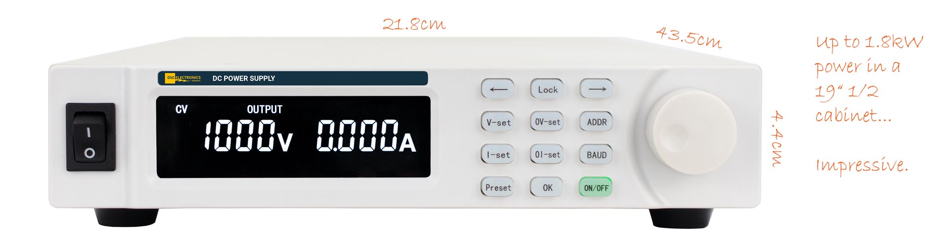
Illustration of a DP30-60M power supply unit. The dimensions of the selected model apply for installation.
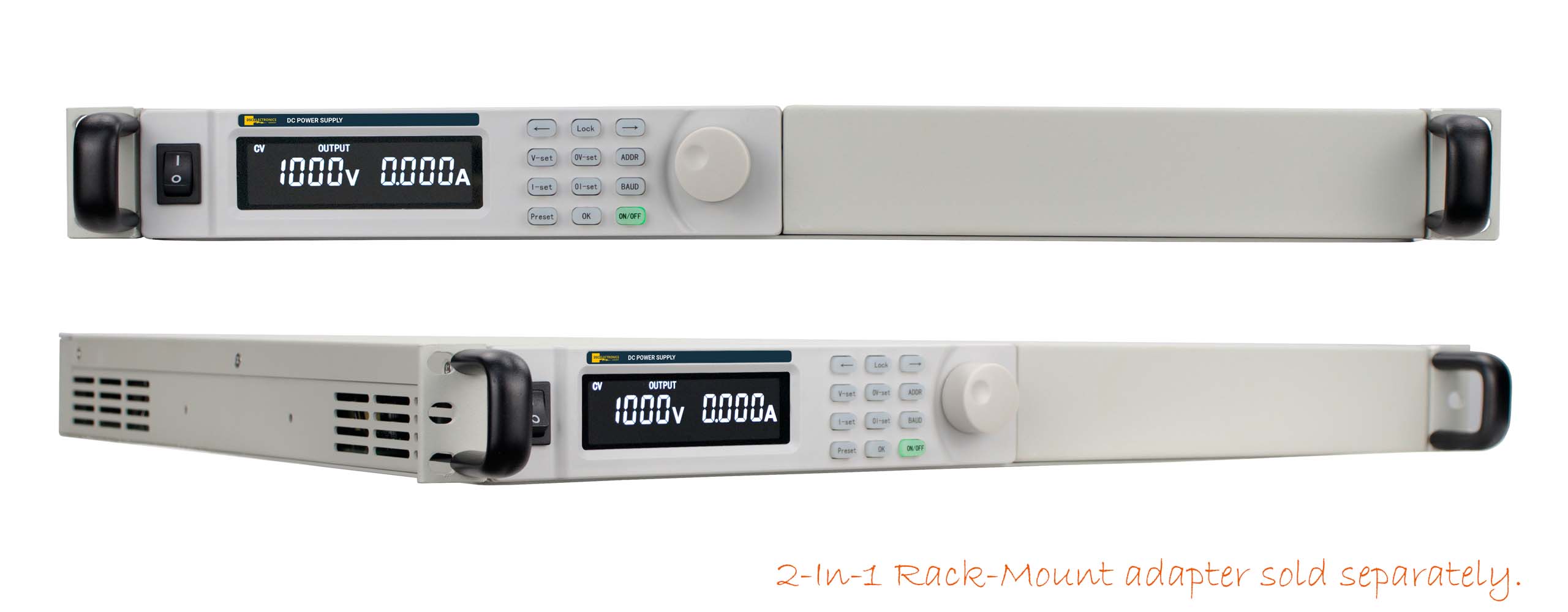
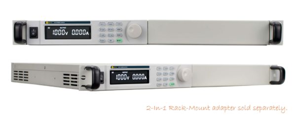
Use the DP-M Series as a standalone unit or integrate it into your rack setup. Compact 1U half-width units can be housed in pairs in a separately available rack insert. Rack mounts are included with full-width units in 2U and 3U configurations.
| Up to and including 1.8 kW | 19-inch half-width, 1U |
| Over 1.8 kW up to and including 12 kW | 19-inch full-width, 2U |
| More than 12kW | 19-inch full-width, 3U |
For certain models, particularly those rated for higher voltages, the enclosure size may vary. The model dimensions and the confirmed version are authoritative.
If a single power supply unit is not sufficient, expand your DC power supply with a master/slave parallel system consisting of DP-M full-width units equipped with the appropriate parallel components. The voltage range remains the same, while the available current increases with the number of modules. The following example systems range from 20 V to 2,000 V and each provide more current than a single standard model in the series can deliver at the specified voltage.
For each voltage range shown, the examples use six units of the standard model with the highest rated current. The maximum output voltage, total current, and calculated system power are specified. One unit is configured as the master, and the other five as slaves. With the DP-M series, this role is set on the unit itself; separate master and slave versions are not required. The examples refer exclusively to full-width devices.
| Max. System Voltage | Max. Total Current | Max. System Performance* | Performance Modules | Equipment height in a 19-inch rack |
|---|---|---|---|---|
| 20V | 3600A | 72 kW | 6 × DP20-6HM | 18HE |
| 30V | 3000A | 90 kW | 6 × DP30-5HM | 18HE |
| 60V | 1500A | 90 kW | 6 × DP60-250M | 18HE |
| 100V | 900A | 90 kW | 6 × DP1H-150M | 18HE |
| 150V | 600A | 90 kW | 6 × DP150-1HM | 18HE |
| 300V | 300A | 90 kW | 6 × DP3H-50M | 18HE |
| 600V | 150A | 90 kW | 6 × DP6H-25M | 18HE |
| 1000V | 90A | 90 kW | 6 × DP10H-15M | 18HE |
| 1500V | 60A | 90 kW | 6 × DP15H-10M | 18HE |
| 2000V | 30A | 60 kW | 6 × DP20H-5M | 18HE |
* System power is calculated based on the listed voltage and current limits and is limited to the sum of the modules' rated powers. The HE specification refers only to the height of the units. Additional space for cooling, cabling, and protective components must be planned for separately.
We tailor the number of modules, system configuration, power connection, and protective circuitry to your test setup. In parallel operation, an external analog control is not available on either the master or the slaves. For loads with energy recovery, a properly designed protection concept is required. Parallel operation does not turn the power supply into an energy sink.
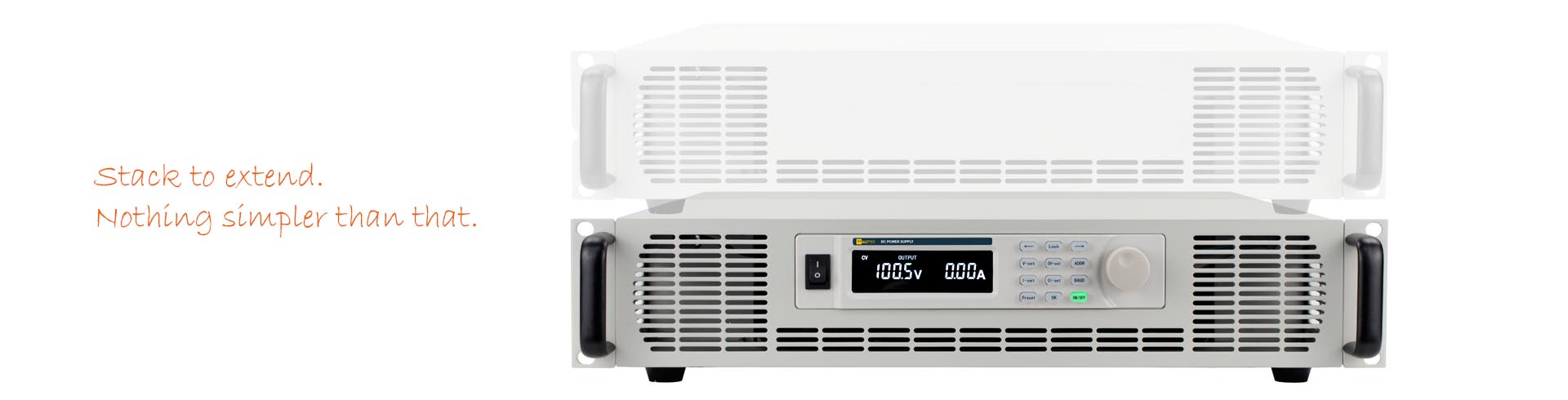
Illustration of a DP-M power supply with an AP8 module. The expansion unit is custom-built to match the power supply and the application.
Expand the capabilities of your DP-M system with external modules tailored to your specific needs. Whether you need additional filtering, polarity reversal, or mechanical isolation: The electrical and mechanical design will be customized to match your power supply and test setup.
Integrated reverse-current protection and additional protection modules
The output rectifier stage already provides basic protection against same-polarity reverse currents within the device’s permissible limits. For high-energy loads or reverse voltage transients, the protection can be specifically enhanced. The power supply is not an energy sink with unlimited capacity. The required design depends on the reverse current, reverse voltage, and stored load energy.
Model AP9: Application-Specific Reverse Current and Reverse Voltage Protection
With the AP9, you can tailor the additional protection to demanding inductive or capacitive loads. The module is custom-manufactured to order for the expected currents, voltages, and energy levels. Options include a combined protection circuit against high reverse currents and reverse voltages—particularly reverse-polarity transients—or a design as an active braking chopper to convert regenerated energy into heat. The specifications and permissible duty cycles will be agreed upon to suit your test setup.
Model AP8: Additional output-side EMC filter with
capacitance. To meet increased demands on your load’s power supply, the AP8 combines a three-stage EMC filter with additional output capacitance. The module helps reduce conducted interference and stabilizes the power supply to demanding loads. The design takes into account the power supply unit, the load, and the desired dynamic response.
Model AP7: Additional input-side EMC filter
When there are increased requirements on the mains side, the AP7 supplements the existing filtering with a three-stage EMC filter. This helps reduce conducted interference in demanding test and production environments. The single- or three-phase configuration and current-carrying capacity are selected to match the power supply unit.
Model AP6: Polarity Reverser
Change the output polarity to match your test procedure. The AP6 can be controlled via the power supply unit’s digital communication using Modbus RTU, or directly on the module via a 5V input or the front-panel switch. During the polarity change, power to the load is interrupted for a maximum of 2 seconds. The configuration is tailored to the power supply unit and the application.
Model AP5: Mechanical Isolation of the Load
Supplement the electronic output control with a physical isolation point between the power supply and the load or test bench. The AP5 is manufactured to match the voltage, current, and application, and is integrated into your system’s safety concept.
All AP modules are manufactured to order. The cabinet , and electrical specifications are tailored to your application.
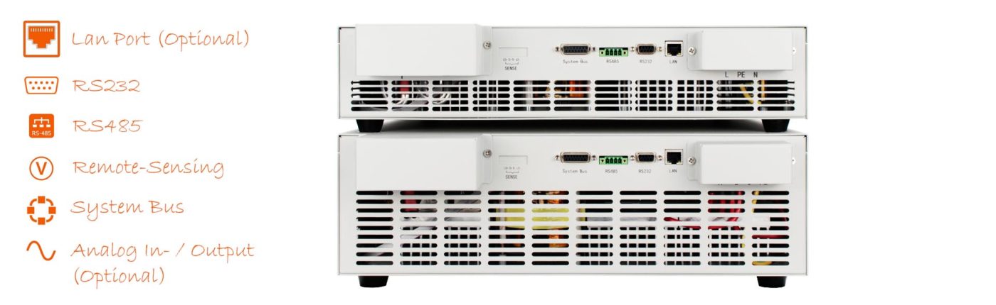
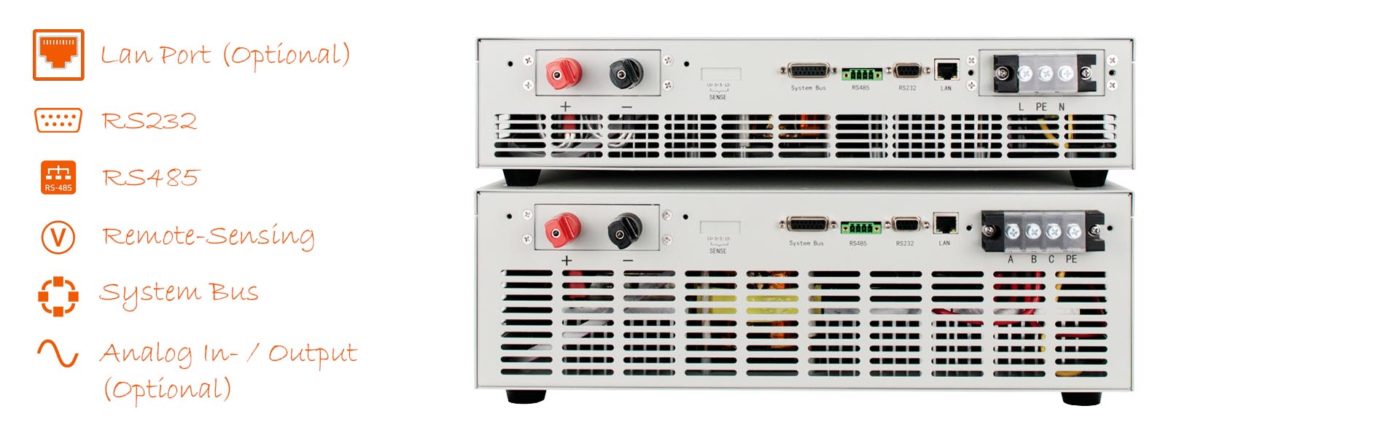
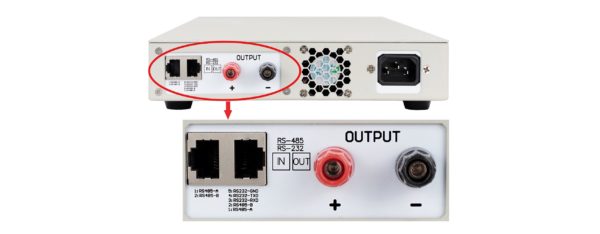
RS232 and RS485 (standard)
Both serial interfaces support Modbus RTU. The documented protocol facilitates integration into existing control systems and custom automation solutions.
[D4] LAN (optional)
Add a LAN interface to the digital connection for your higher-level controller.
remote-sensing input (Standard)
Regulate the voltage where it's needed: The remote-sensing input measures it directly at the load and compensates for line losses of up to 2V. This ensures a precise power supply, especially with high currents and longer connection cables.
[A1] Interlock Loop (included in the optional analog package)
An open loop blocks the output; a closed loop enables it. This allows you to incorporate an external enable condition into your test setup. The following analog functions—U, L, F, and G—are included with A1 as a complete package. Select 0 … 5V, 0 … 10V, or 4 … 20mA for all four analog functions collectively.
[U] External analog control U (in the analog package)
Output voltage set via 0 … 10 V (U1), 0 … 5 V (U2), or 4 … 20 mA (U3).
[L] External Analog Control I (in the Analog Package)
Output current set via 0 … 10 V (L1), 0 … 5 V (L2), or 4 … 20 mA (L3).
[F] External analog feedback U (in the analog package)
Output of the actual voltage value via 0 … 10 V (F1), 0 … 5 V (F2), or 4 … 20 mA (F3).
[G] External Analog Feedback I (in the Analog Package)
Output of the actual current value via 0 … 10 V (G1), 0 … 5 V (G2), or 4 … 20 mA (G3). The signals are provided via the system bus connection in accordance with the ordered configuration.
| Weight | 5 kg |
|---|---|
| Dimensions | 4.4 H cm x 21.8 W cm x 43.5 D cm |
| Manufacturer | DSC-Electronics Germany |
| Series | DP-M Series |
| Input voltage | 207 ... 253VAC |
| Input frequency | 47 ... 63Hz |
| Efficiency (100% load) | 85% |
| Output type | Variable DC |
| Output configuration | Floating |
| Output voltage | 0 ... 1kV |
| Output current | 0 ... 1A |
| Power | 0 ... 1kW |
| Load regulation U | ≤0.1% FS |
| Load regulation I | ≤0.1% FS |
| Line regulation U | ≤0.2% FS |
| Line regulation I | ≤0.2% FS |
| Display resolution U | 1V |
| Display resolution I | 1mA |
| Display accuracy U | ≤0.1% FS + 100mV |
| Display accuracy I | ≤0.3% FS + 10mA |
| Setting resolution U | 1V |
| Setting resolution I | 1mA |
| Setting accuracy U | ≤0.1% FS + 100mV |
| Setting accuracy I | ≤0.3% FS + 10mA |
| Residual ripple U | ≤0.3% FS + 100mV (rms) |
| Residual ripple I | ≤0.3% FS + 10mA (rms) |
| Temperature coefficient U | ≤0.1% FS rms/℃ |
| Temperature coefficient I | ≤0.3% FS rms/℃ |
| Recovery time | ≤5ms |
| Command response time | 50ms |
| Functionality | Compatible with AP Series expansion modules, CC - constant current mode, CV - constant voltage mode |
| Reverse current protection | Integrated, passive (same-polarity return currents) |
| Telemetering compensation | No |
| Parallel connection | Not specified |
| Series connection | No |
| Digital communication | LAN, RS232, RS485 |
| Communication protocol | Modbus RTU |
| Feedback output I | 0 ... 5V signal, 0 ... 10V signal, 4 ... 20mA signal, No |
| Feedback output P | No |
| Feedback output U | 0 ... 5V signal, 0 ... 10V signal, 4 ... 20mA signal, No |
| External control signal I | 0 ... 5V signal, 0 ... 10V signal, 4 ... 20mA signal, No |
| External control signal U | 0 ... 5V signal, 0 ... 10V signal, 4 ... 20mA signal, No |
| Ext. output interlock | Closed/Open Loop, No |
| Certification | CE, ROHS |