
Performance reserves for varying test tasks
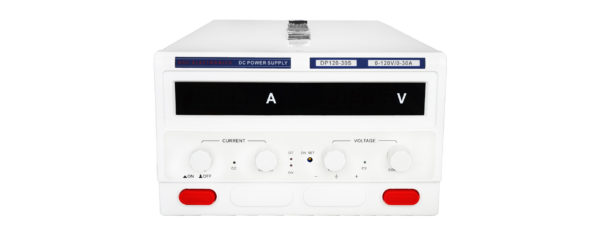
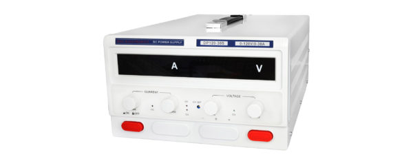
Illustration of a DP-S laboratory power supply. Dimensions and design vary depending on the model selected.

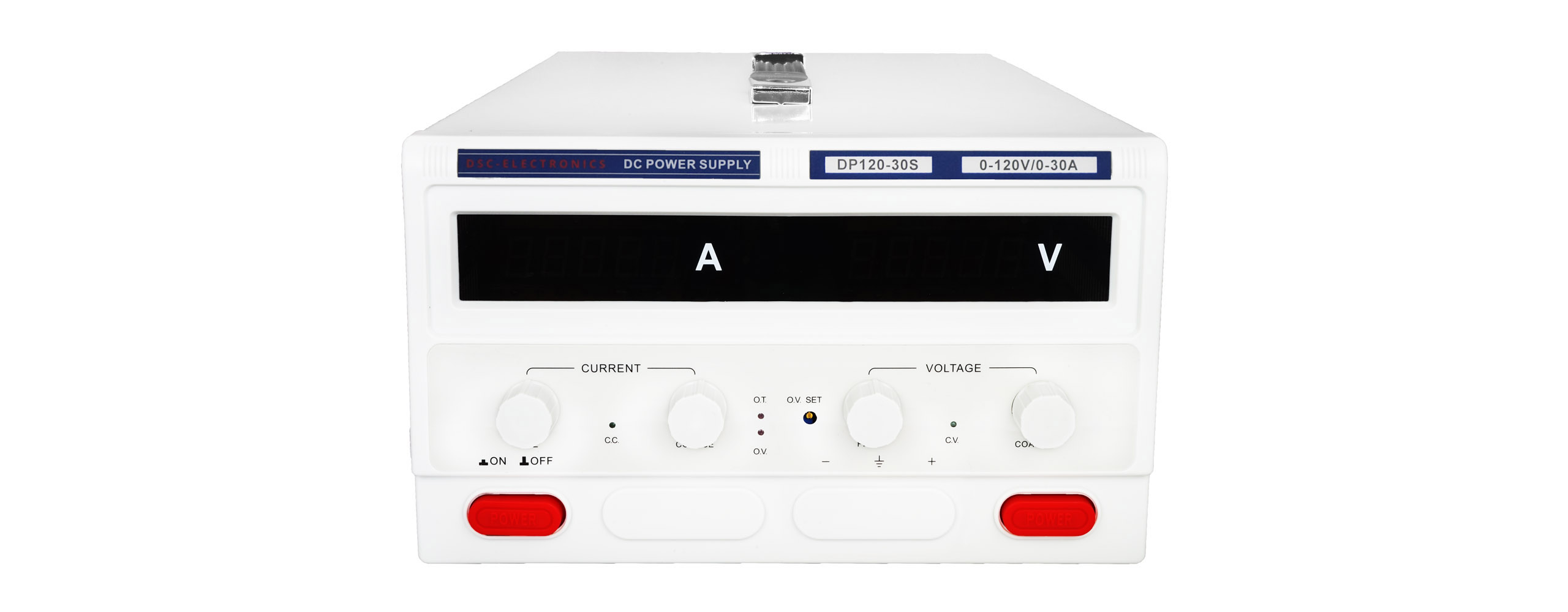
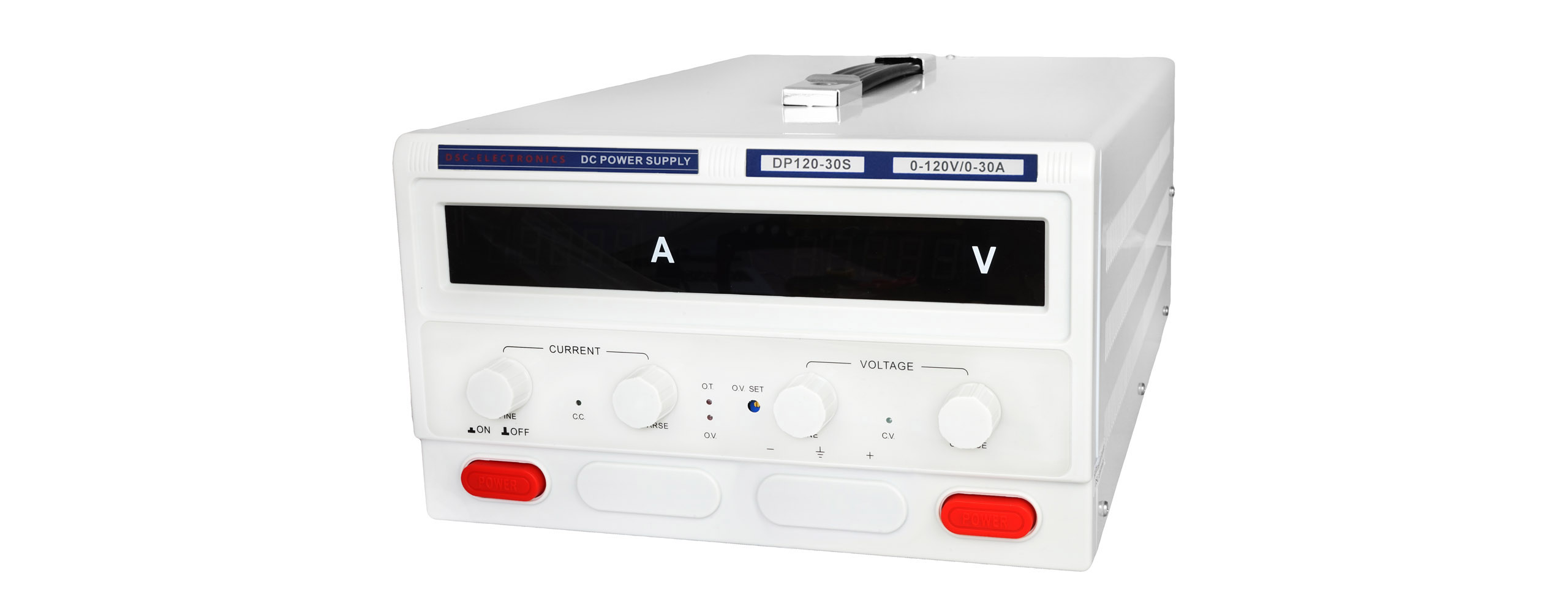
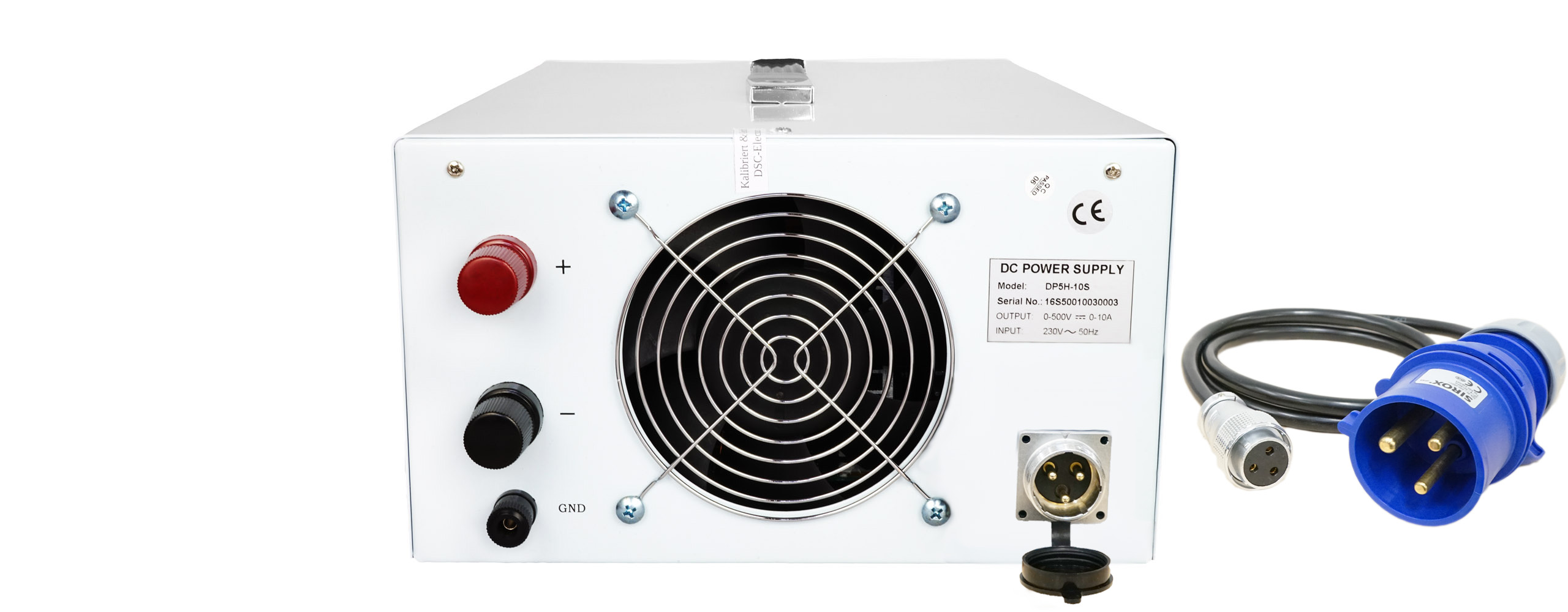
Powerful performance reserves in a compact desktop enclosure: The DP-S Series from DSC-Electronics Germany supports flexible testing and repair tasks with CC/CV control. The standard USB port enables Modbus RTU communication via a virtual COM port. Analog control inputs and interlocks are optional. Continuous operation is possible up to 60% of the model’s rated power. In addition, at least 1 hour of operation at the rated power is available at an ambient temperature of 25°C.
Deliver high power exactly where you need it: The compact DP-S Series laboratory power supplies are designed for testing, repair, and development tasks that require a portable power supply with substantial power reserves. Whether testing inverters, powering heating elements, or testing batteries and capacitor banks: The benchtop enclosure with a carrying handle facilitates flexible use at various workstations.
Voltage and current can be conveniently adjusted using separate coarse and fine controls. The digital control system supports constant-voltage and constant-current (CV/CC) operation with automatic switching based on the load. The standard USB port enables communication with Modbus RTU via a virtual COM port. Optional analog control inputs provide additional connectivity to your test setup.
| Connectivity | USB with a virtual COM port and Modbus RTU as standard. Optional analog control of voltage and current via 0 … 5 V, 0 … 10 V, or 4 … 20 mA, as well as an interlock loop. |
| Functionality | CC/CV operation within the model-specific setting ranges. Continuous operation is possible up to 60% of the respective rated power. Beyond that, the unit can operate at rated power for at least 1 hour at an ambient temperature of 25°C. |
| Output configuration | Potential-free, short-circuit-proof output. No remote measurement. |
| Safety | Protection against overheating, overvoltage, and overcurrent. Complete output shutdown for cooling when the heat sink temperature reaches 85°C. |
| extensibility | Application-specific expansion via AP9 and AP8. |
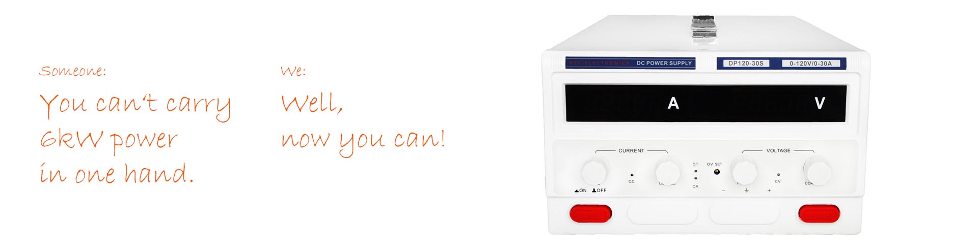
Illustration of a DP-S laboratory power supply. Dimensions and design vary depending on the model selected.
The DP-S Series offers a practical alternative when a large stationary power supply is not required at the application site. The wide range of models allows you to select the appropriate voltage, current, and power ranges. For longer endurance tests, the following operating profile should be taken into account.
Continuous Operation and Temporary Full Load
| Up to and including 60% of the model-specific rated power | Continuous operation |
| Over 60% to 100% of the model-specific rated power | At least 1 hour at an ambient temperature of 25°C |
| Heat sink temperature reaches 85°C | The output is completely shut off and the device cools down |
The current operating status is displayed on the front panel. The cooling phase involves shutting down the output, not merely reducing power. The rated power and the specified cooling conditions for the selected model apply when designing your test cycle.
Coarse and fine adjustment for voltage and current
Two rotary controls each allow for quick setting of the desired range and subsequent fine-tuning. Bright four-digit LED displays show the voltage and current. Additional status indicators provide information on operating and error conditions.
Remote control compatible with your system
USB with a virtual COM port is included as standard in the current version. Analog control inputs for voltage and current, as well as an interlock loop, can be ordered as options. The analog connections are accessible from the front via a shielded connector, ensuring convenient integration even in tight test setups.
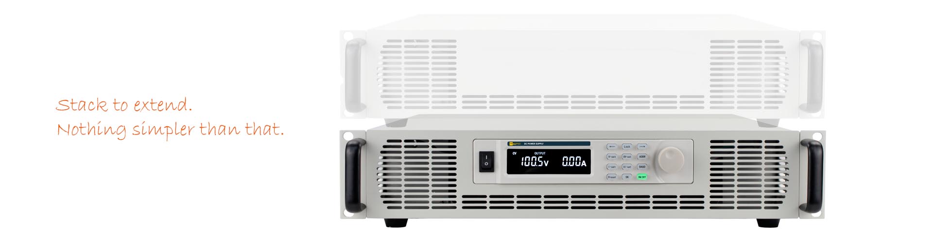
Illustration of a DP-M power supply with an AP8 module. The expansion unit is custom-built to match the power supply and the application.
Integrated reverse-current protection and additional protection modules
The output rectifier stage already provides basic protection against same-polarity reverse currents within the device’s permissible limits. For high-energy loads or reverse voltage transients, the protection can be specifically enhanced. The power supply is not an energy sink with unlimited capacity. The required design depends on the reverse current, reverse voltage, and stored load energy.
Model AP9: Application-Specific Reverse Current and Reverse Voltage Protection
With the AP9, you can tailor the additional protection to demanding inductive or capacitive loads. The module is custom-manufactured to order for the expected currents, voltages, and energy levels. Options include a combined protection circuit against high reverse currents and reverse voltages—particularly reverse-polarity transients—or a design as an active braking chopper to convert regenerated energy into heat. The specifications and permissible duty cycles will be agreed upon to suit your test setup.
Model AP8: Additional output-side EMC filter with
capacitance. To meet increased demands on your load’s power supply, the AP8 combines a three-stage EMC filter with additional output capacitance. The module helps reduce conducted interference and stabilizes the power supply to demanding loads. The design takes into account the power supply unit, the load, and the desired dynamic response.
All AP modules are manufactured to order. The cabinet , and electrical specifications are tailored to your application.
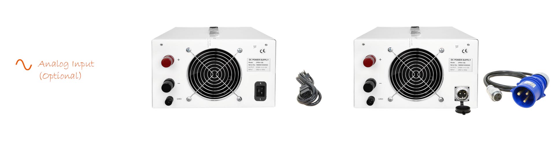
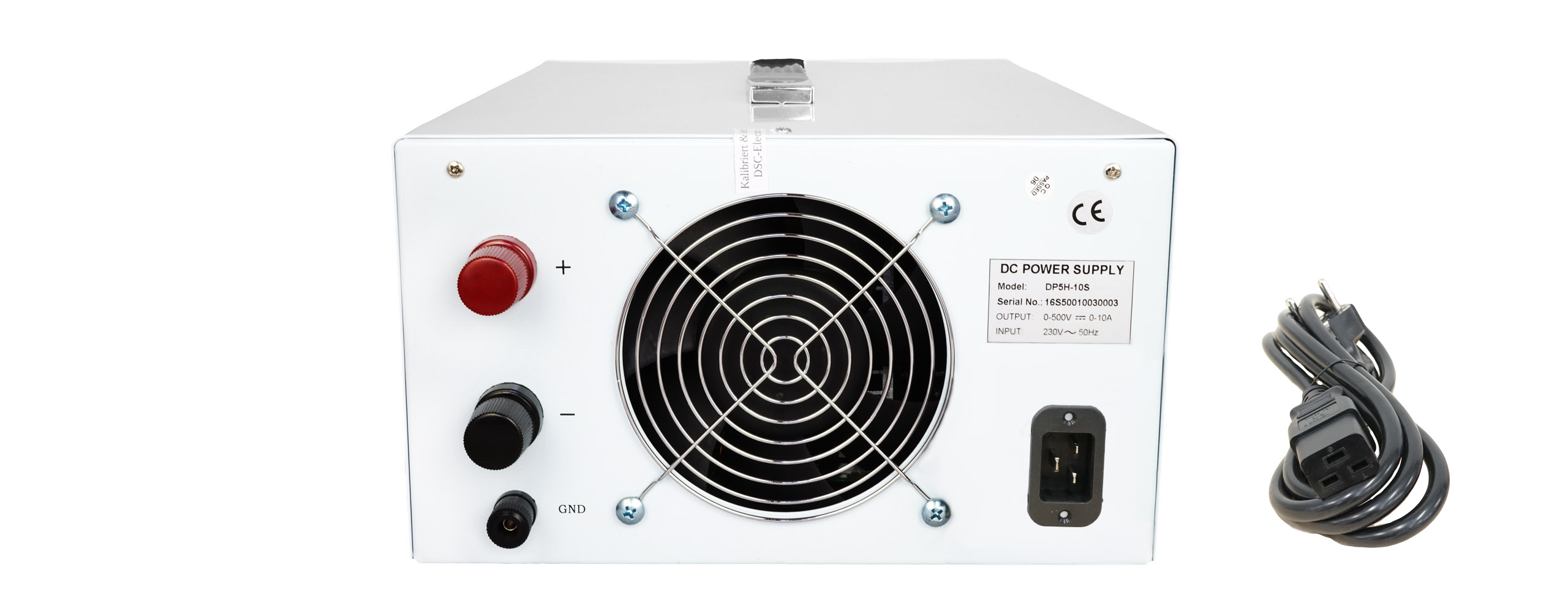
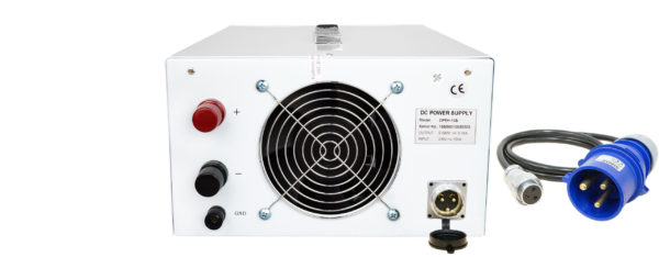
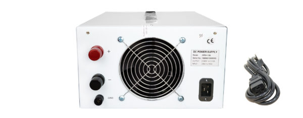
Illustration of the DP-S series. The connections vary depending on the model, revision, and selected features.
Single-phase power connection
Even the more powerful DP-S models are powered by a single-phase supply. Depending on the model, C19/C20 connectors or appropriately rated connectors with pull-out protection are used. A suitable connection cable is included with the unit. For 6 kW models, a properly sized power supply with a 32 A fuse is required. The device-specific connection data applies.
USB with Virtual COM Port (Standard)
Connect the power supply to your computer via USB. The CH341SER driver provides a virtual COM port that allows you to set and retrieve output values using Modbus RTU. The device does not have a native RS-232 port. The documented protocol simplifies integration into existing control systems and custom test programs. This allows you to digitally integrate settings and measured values into your workflow.
[A1] Interlock loop (optional)
An open loop blocks the output; a closed loop enables it. This allows an external enable condition to be incorporated into the test setup. Output enable requires the device to be in the appropriate operating state.
[U] External analog control U (optional)
Specify the output voltage as 0 … 10 V (U1), 0 … 5 V (U2), or 4 … 20 mA (U3).
[L] External Analog Control I (optional)
The output current can be set to 0 … 10 V (L1), 0 … 5 V (L2), or 4 … 20 mA (L3). The analog signals are routed through the front-panel DIN connector. The matching connector is included with the unit if the appropriate configuration is selected.
| Weight | 8 kg |
|---|---|
| Dimensions | 16 H cm x 26 W cm x 38 D cm |
| Manufacturer | DSC-Electronics Germany |
| Series | DP-S Series |
| Input voltage | 207 ... 253VAC |
| Input frequency | 47 ... 63Hz |
| Efficiency (100% load) | 85% |
| Output type | Variable DC |
| Output configuration | Floating |
| Output voltage | 0 ... 50V |
| Output current | 0 ... 50A |
| Power | 0 ... 2.5kW |
| Load regulation U | ≤0.5% + 2 dig |
| Load regulation I | ≤0.5% + 2 dig |
| Line regulation U | ≤0.2% + 2 dig |
| Line regulation I | ≤0.5% + 2 dig |
| Display resolution U | 10mV |
| Display resolution I | 10mA |
| Display accuracy U | ±1%FS ± 1 dig |
| Display accuracy I | ±1%FS ± 1 dig |
| Setting resolution U | 10mV |
| Setting resolution I | 10mA |
| Setting accuracy U | ±0.5% reading ± 2 dig |
| Setting accuracy I | ±1% reading ± 2 dig |
| Residual ripple U | ≤1%FS (rms) |
| Residual ripple I | ≤1%FS (rms) |
| Functionality | CC - Constant Current Mode, CV - Constant Voltage Mode |
| Reverse current protection | Integrated, passive (same-polarity return currents) |
| Telemetering compensation | No |
| Parallel connection | Not specified |
| Series connection | No |
| Digital communication | USB |
| Feedback output I | No |
| Feedback output P | No |
| Feedback output U | No |
| External control signal I | 0 ... 5V signal, 0 ... 10V signal, 4 ... 20mA signal |
| External control signal P | No |
| External control signal U | 0 ... 5V signal, 0 ... 10V signal, 4 ... 20mA signal |
| Ext. output interlock | Closed/Open Loop |
| Certification | CE, ROHS |
| Communication protocol | Modbus RTU |