

For laboratory workstations and racks
Illustration of a DP-HV power supply unit. cabinet and the connection configuration depend on the selected model.

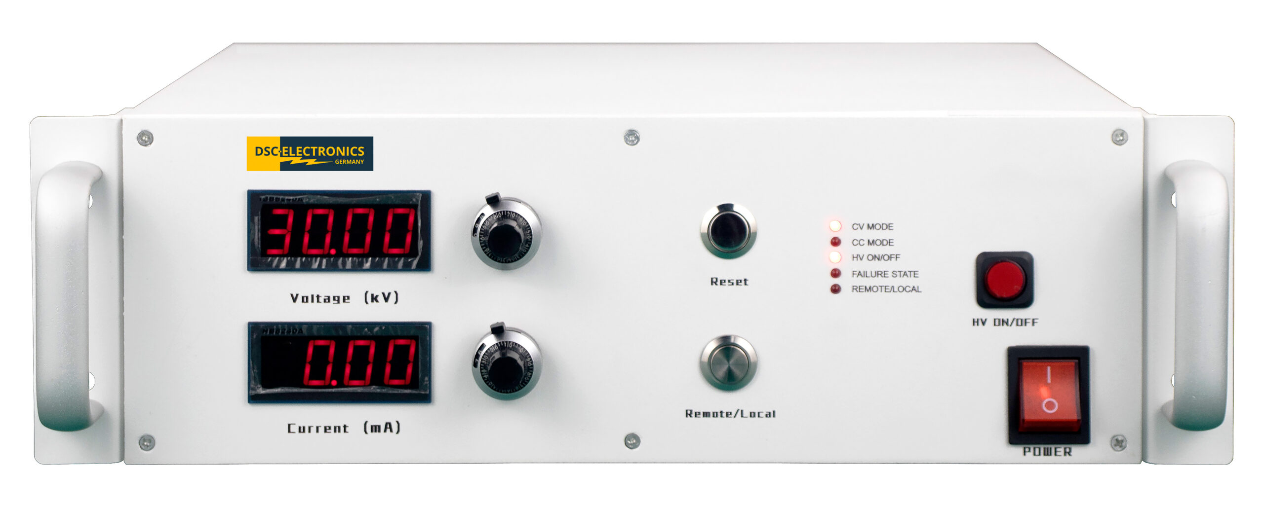


High-voltage power supplies tailored to your application: The DP-HV series from DSC-Electronics Germany combines regulated CC/CV operation, intuitive front-panel controls, and comprehensive protection functions. Analog 0 … 10V I/O is included as standard and can be replaced by RS485 with Modbus RTU. The standard interlock loop remains intact. The output is grounded and is supplied with the positive or negative polarity specified in the order.
Targeted Use of High Voltage: The DP-HV Series offers regulated DC voltage and constant current power supplies for insulation testing, electrostatic applications, and demanding tasks in laboratories and industry. The wide range of standard models and custom designs up to 300 kV allows you to select a power supply that matches your voltage range, load, and test procedure.
Easy-to-read LED displays, lockable precision rotary controls, and the option of local or remote operation support a well-organized workflow. Analog control and measurement interfaces are included as standard features. Alternatively, the device can be integrated into automated test stands via RS485 and Modbus RTU. The standard interlock loop remains available even in this digital version.
| Connectivity | Analog 0 … 10V control and measured value feedback are standard. Optional RS485 with Modbus RTU instead of analog I/O. The interlock loop remains intact. |
| Functionality | Constant-voltage and constant-current (CV/CC) operation with automatic switching. Local operation or external control. |
| Output configuration | Grounded output with positive or negative high voltage, depending on the version ordered. No remote measurement. |
| Safety | Protection against overvoltage, overcurrent, overtemperature, and short circuits, as well as arc protection and a standard interlock loop. |
| Accuracy | Voltage and current settings and display: ±0.5% FS, ±2 digits resolution; other specifications are listed by model. |
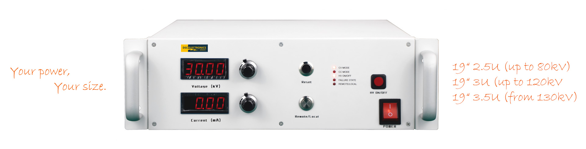
Illustration of a DP-HV power supply unit. cabinet and the connection configuration depend on the selected model.
The DP-HV series combines high output voltages with compact enclosures. A temperature-dependent fan control system adjusts cooling to match operating conditions. Depending on the model, the units can be used as freestanding units or mounted in a rack. The required rack mounts are included with the unit.
| Models up to and including 80 kV | 19-inchcabinet, typically 2.5U |
| Models rated from 80 kV up to and including 120 kV | 19-inchcabinet, typically 3U |
| Models rated above 120 kV | 19-inchcabinet, typically 3.5U |
The dimensions of the selected model are critical for installation planning. Custom versions may vary. The maximum values for the series include customer-specific units and cannot be achieved simultaneously with every standard model.
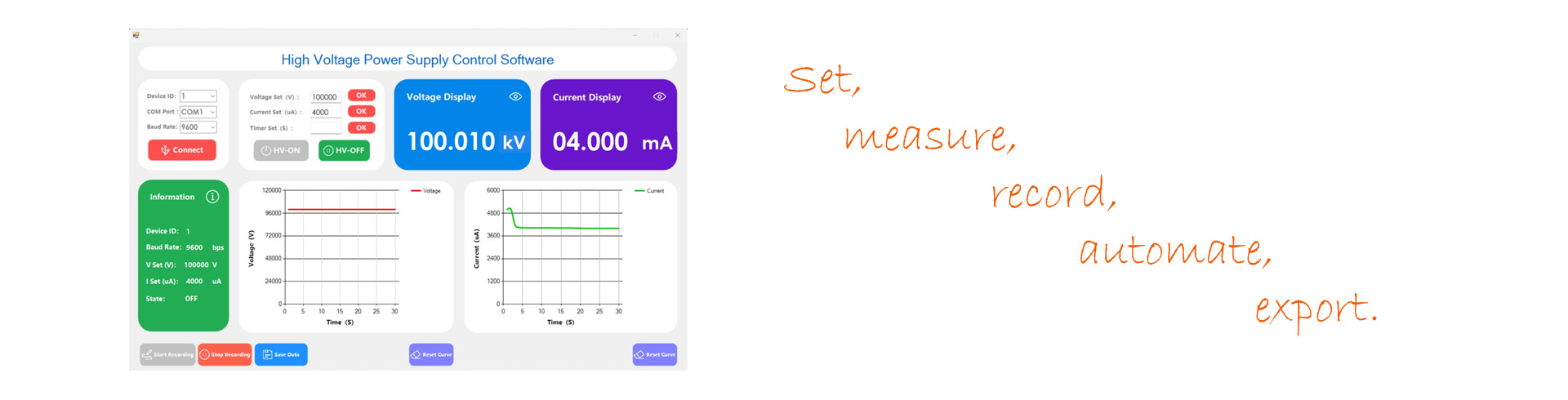
Representative image of the software for the DP-HV series.
With the optional RS485 interface, you can set output values digitally and read measured values via Modbus RTU. The included Windows software supports remote control and data logging. The documented protocol simplifies integration into your own test programs. This allows you to automate recurring tasks and record results in a traceable manner.
Tailor Protection to the Load
The output rectifier stage already provides basic protection against same-polarity reverse currents within the device’s permissible limits. For high-energy loads or reverse voltage transients, a suitable additional protective circuit must be provided. The power supply is not an energy sink with unlimited capacity. In particular, when switching off inductive loads and when discharging capacitors, current, voltage, and load energy must remain within the agreed limits.
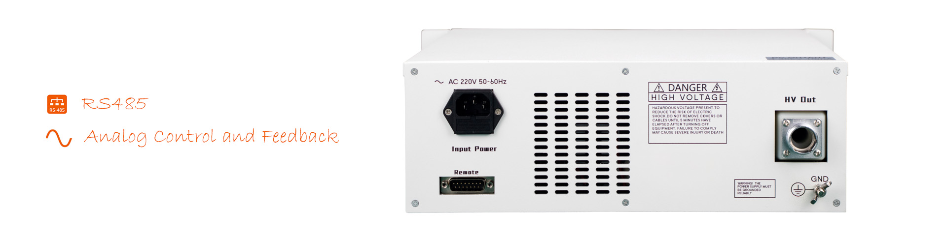
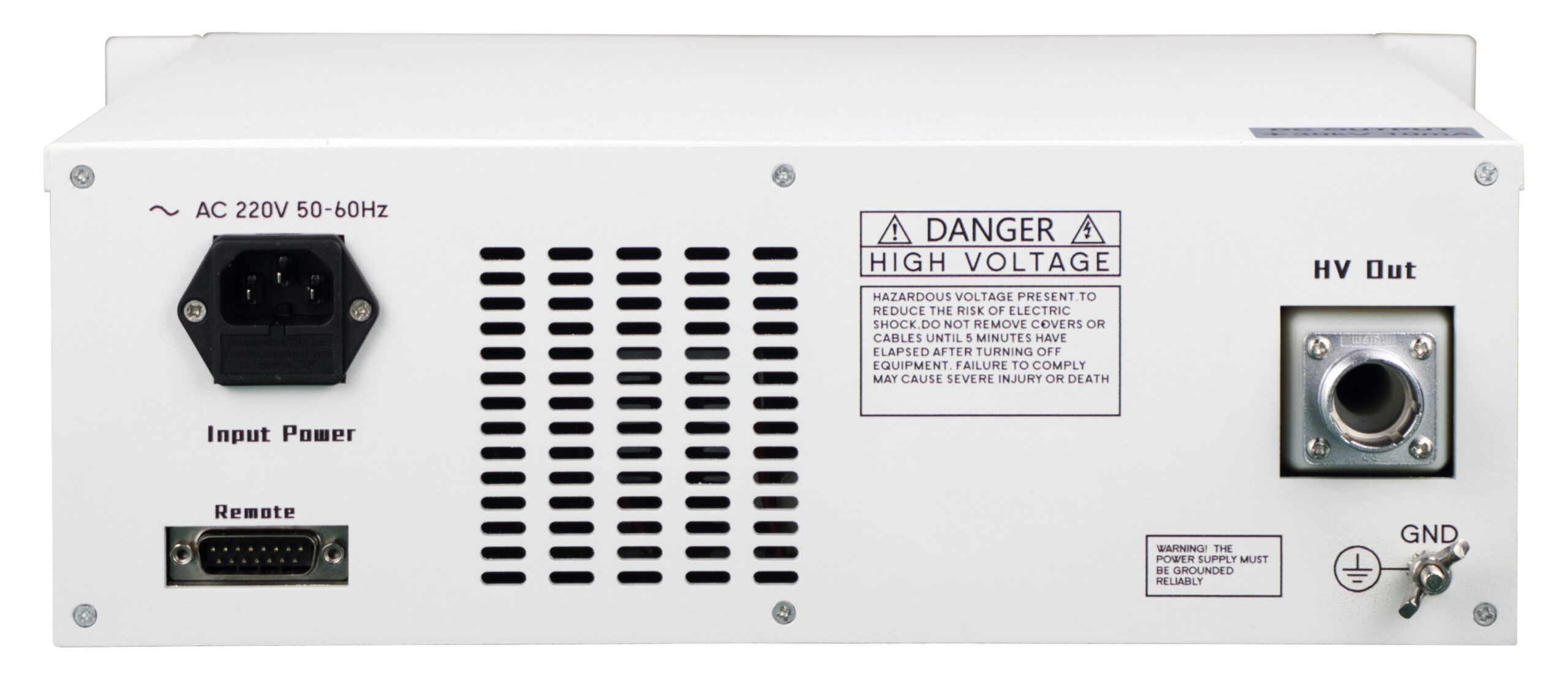
Illustration of the back panel. The pin assignment depends on the configuration ordered.
Analog I/O (Standard)
Using 0 … 10 V signals, you can set the output voltage and output current and read their actual values. Four active-low open-collector outputs indicate voltage mode, current mode, error status, and the HV output status. A +15 V auxiliary reference with a maximum load capacity of 50 mA completes the interface.
Interlock Loop (Standard)
The loop on pins 9 and 10 is also present in models equipped with RS485. In local operation, a closed loop enables the output, while an open loop disables it. In remote operation, the loop controls the output externally. The operating and connection requirements for the ordered model are described in the manual.
RS485 with Modbus RTU (optional)
The digital version replaces the analog I/O. Analog setpoint input, measured value feedback, status outputs, and auxiliary reference are then not available in parallel. The interlock loop remains intact. This allows the external output enable to be used even in a digitally controlled test stand.
DB15 Pinout for the Standard Analog Version
| Pin | Function | Signal / Power Handling Capacity |
|---|---|---|
| 1 | Voltage Specification | 0 … 10 V for 0 … 100% of the rated value |
| 2 | GND | Signal Ground |
| 3 | Current Setting | 0 … 10 V for 0 … 100% of the rated value |
| 4 | GND | Signal Ground |
| 5 | Actual Voltage Value | 0 … 10 V for 0 … 100% of the rated value |
| 6 | GND | Signal Ground |
| 7 | Actual Current Value | 0 … 10 V for 0 … 100% of the rated value |
| 8 | Reset | High level, maximum 15 V |
| 9–10 | Interlock / Output Control | Closed-loop or open-loop; depending on whether the system is operating locally or remotely |
| 11 | Constant Voltage (CV) Operation | Open collector, active-low; maximum 35 V / 10 mA |
| 12 | Power Operation (CC) | Open collector, active-low; maximum 35 V / 10 mA |
| 13 | Error Status | Open collector, active-low; maximum 35 V / 10 mA |
| 14 | HV Initial Status | Open collector, active-low; maximum 35 V / 10 mA |
| 15 | Help Reference | +15V, maximum 50mA |
The table applies to the standard analog version. For devices with RS485, the corresponding digital pin assignment applies.
| Weight | 14 kg |
|---|---|
| Dimensions | 11.0 H cm x 37.6 W cm x 36.7 D cm |
| Manufacturer | DSC-Electronics Germany |
| Series | DP-HV Series |
| Input voltage | 207 ... 253VAC |
| Input frequency | 47 ... 63Hz |
| Efficiency (100% load) | 85% |
| Output type | Variable DC |
| Output configuration | Positive, earthed, Negative, earthed |
| Output voltage | 0 to 30kV |
| Output current | 0 … 0.01A |
| Power | 0 ... 300W |
| Load regulation I | ≤1% FS |
| Line regulation U | ≤1% FS |
| Line regulation I | ≤1% FS |
| Display resolution U | 10V |
| Display resolution I | 0.01mA |
| Display accuracy U | ±0.5% of full scale ± 2 digits |
| Display accuracy I | ±0.5% of full scale ± 2 digits |
| Setting resolution U | 10V |
| Setting resolution I | 0.01mA |
| Setting accuracy U | ±0.5% of full scale ± 2 digits |
| Setting accuracy I | ±0.5% of full scale ± 2 digits |
| Residual ripple U | ≤1%FS (rms) |
| Residual ripple I | ≤1%FS (rms) |
| Temperature coefficient U | 100ppm/°C |
| Temperature coefficient I | 100ppm/°C |
| Command response time | 50ms |
| Functionality | CC - Constant Current Mode, CV - Constant Voltage Mode |
| Reverse current protection | Integrated, passive (same-polarity return currents) |
| Telemetering compensation | No |
| Parallel connection | No |
| Series connection | No |
| Digital communication | RS485 |
| Feedback output I | 0 … 10V signal |
| Feedback output P | No |
| Feedback output U | 0 … 10V signal |
| External control signal I | 0 … 10V signal |
| External control signal P | No |
| External control signal U | 0 … 10V signal |
| Ext. output interlock | Closed/Open Loop |
| Certification | CE, ROHS |
| Load regulation U | ≤1% FS |