


Precision in a handy format
Illustration of a DP-H laboratory power supply. Please refer to the technical specifications for the design and dimensions of the selected model.



Precise testing and automation of processes directly on the device: The DP-H Series from DSC-Electronics Germany offers 1 mV / 1 mA resolution, stored test programs, and a battery charging function in a compact cabinet. Standard features include RS232/SCPI, RS485/Modbus RTU, analog 0 … 5 V I/O, and remote measurement up to 2 V.
Deliver precise power, perform repeatable tests, and automate processes directly on the device: The DP-H Series combines the accuracy of a precision laboratory power supply with the convenience of a programmable power supply. A setting and display resolution of 1 mV / 1 mA, digital control, and the clear color display support you in development, measurement, and testing tasks where reproducible output values are critical.
Whether at an individual lab workstation or on an automated test bench: You decide how you work. Stored voltage/current waveforms run without an external computer. For integration into your infrastructure, RS232 with SCPI, RS485 with Modbus RTU, and analog 0 … 5V inputs and outputs are available as standard features. In addition to the resolution, you can find the specific accuracy values in the model’s technical specifications.
| Connectivity | RS232 with SCPI and RS485 with Modbus RTU as standard. Analog control and feedback via 0 … 5 V, as well as an external trigger for programmed sequences. |
| Functionality | CC/CV operation with automatic switching, programmable test cycles, and a battery charging function. Remote measurement to compensate for line losses of up to 2 V. |
| Output configuration | Potential-free, short-circuit-proof output. The available combination of voltage, current, and power depends on the selected model. |
| Safety | Protection against overtemperature, overvoltage, and overcurrent with status indicator and lockable front-panel controls. External program trigger; no safety interlock. |
| extensibility | Application-specific extension via AP9 and AP8. No polarity reversal. |

Illustration of a DP-H laboratory power supply. Please refer to the technical specifications for the design and dimensions of the selected model.
Use your power supply wherever it's needed: The compact design and carrying handle make it easy to move between test stations. A temperature-dependent fan control system with five temperature sensors adjusts the cooling based on the load. The permissible environmental conditions are specified in the manual.

Removable rubber pads protect the front and back from mechanical impact. For stationary use, up to four units can be mounted in a separately available 4U rack insert without the pads. This allows you to create a space-saving test setup with four independently operable channels.
4.3-inch color display and convenient front-panel controls
Setpoints, actual values, and time-series data are clearly displayed. Using the numeric keypad and rotary encoder, you can quickly access the desired setting and enter values directly or adjust them incrementally.
Programmed Voltage and Current Curves: Store up to 300 program steps with voltage, current, and time settings to perform recurring tests without constant readjustment. Programs can run for a specified number of cycles or repeat indefinitely and can be started manually or via an external trigger. You can transfer stored sequences to other devices using a USB drive. No external computer or controller is required for operation.
Programmable Battery Charging Function: Define a charging profile tailored to your battery and integrate repeatable charging tasks into your testing process. Voltage and current can also be logged via an external controller. Charging parameters and protective measures are tailored to the connected battery.
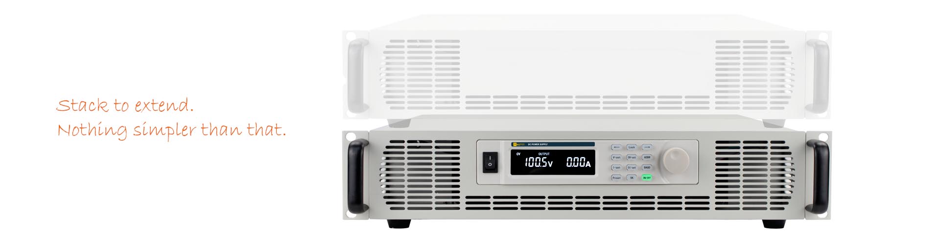
Illustration of a DP-M power supply with an AP8 module. The expansion unit is custom-built to match the power supply and the application.
Integrated reverse-current protection and additional protection modules
The output rectifier stage already provides basic protection against same-polarity reverse currents within the device’s permissible limits. For high-energy loads or reverse voltage transients, the protection can be specifically enhanced. The power supply is not an energy sink with unlimited capacity. The required design depends on the reverse current, reverse voltage, and stored load energy.
Model AP9: Application-Specific Reverse Current and Reverse Voltage Protection
With the AP9, you can tailor the additional protection to demanding inductive or capacitive loads. The module is custom-manufactured to order for the expected currents, voltages, and energy levels. Options include a combined protection circuit against high reverse currents and reverse voltages—particularly reverse-polarity transients—or a design as an active braking chopper to convert regenerated energy into heat. The specifications and permissible duty cycles will be agreed upon to suit your test setup.
Model AP8: Additional output-side EMC filter with
capacitance. To meet increased demands on your load’s power supply, the AP8 combines a three-stage EMC filter with additional output capacitance. The module helps reduce conducted interference and stabilizes the power supply to demanding loads. The design takes into account the power supply unit, the load, and the desired dynamic response.
All AP modules are manufactured to order. The cabinet , and electrical specifications are tailored to your application.

Schematic illustration of the connections on a DP-H laboratory power supply. The position and design may vary depending on the revision.
RS232 and RS485 (standard)
RS232 uses SCPI; RS485 uses Modbus RTU. Documented protocols and included LabVIEW examples make it easier to develop custom control solutions and integrate the system with existing test benches.
remote-sensing input (Standard)
Regulate the voltage where it's needed: The remote-sensing input measures it directly at the load and compensates for line losses of up to 2V. This ensures a precise power supply, especially with high currents and longer connection cables.
External Trigger (Standard)
Start or interrupt saved automatic sequences using an external signal. This allows you to coordinate program execution with other steps in your test process. The program trigger is not a safety interlock. A separate interlock loop for external blocking and enabling of the output is available upon request.
Analog Inputs and Outputs (Standard)
Use 0 … 5V signals to set voltage and current values and read their actual values. Additional connections are provided for output control, triggering, and status feedback. A 5V reference simplifies the connection of external potentiometers. See the manual for the exact pin assignment.
| Weight | 6 kg |
|---|---|
| Dimensions | 8.9 H cm x 21.5 W cm x 41.2 D cm |
| Manufacturer | DSC-Electronics Germany |
| Series | DP-H Series |
| Input voltage | 207 ... 253VAC |
| Input frequency | 47 ... 63Hz |
| Efficiency (100% load) | 85% |
| Output type | Variable DC |
| Output configuration | Floating |
| Output voltage | 0 ... 15V |
| Output current | 0 ... 60A |
| Power | 0 ... 900W |
| Load regulation U | ≤0.1% + 5mV |
| Load regulation I | ≤0.1% + 5mA |
| Line regulation U | ≤0.01% + 4mV |
| Line regulation I | ≤0.1% + 3mA |
| Display resolution U | 1mV |
| Display resolution I | 1mA |
| Display accuracy U | ±0.02% reading + 5mV |
| Display accuracy I | ±0.1% reading + 0.1%FS |
| Setting resolution U | 1mV |
| Setting resolution I | 1mA |
| Setting accuracy U | ±0.03% reading + 10mV |
| Setting accuracy I | ±0.1% reading + 0.1%FS |
| Residual ripple U | ≤2mVrms / ≤30mVpp |
| Residual ripple I | ≤10mArms |
| Temperature coefficient U | 100ppm/°C |
| Temperature coefficient I | 150ppm/°C |
| Recovery time | ≤1.5ms |
| Voltage rise time | ≤300ms (100% load) |
| Voltage drop time | ≤2ms (100% load) |
| Command response time | 50ms |
| Functionality | CC - Constant Current Mode, CV - Constant Voltage Mode, Programmable Battery Charge Function |
| Reverse current protection | Integrated, passive (same-polarity return currents) |
| Telemetering compensation | Up to 2V |
| Parallel connection | Not specified |
| Series connection | No |
| Digital communication | RS232, RS485 |
| Communication protocol | Modbus RTU via RS485, SCPI via RS232 |
| Feedback output I | 0 ... 5V signal |
| Feedback output P | No |
| Feedback output U | 0 ... 5V signal |
| External control signal I | 0 ... 5V signal |
| External control signal P | No |
| External control signal U | 0 ... 5V signal |
| Ext. output interlock | Closed/Open Loop |
| Certification | CE, ROHS |