
Suitable for laboratory workstations and racks
Illustrative image of the DP-PH series. The dimensions of the selected model apply for installation planning.

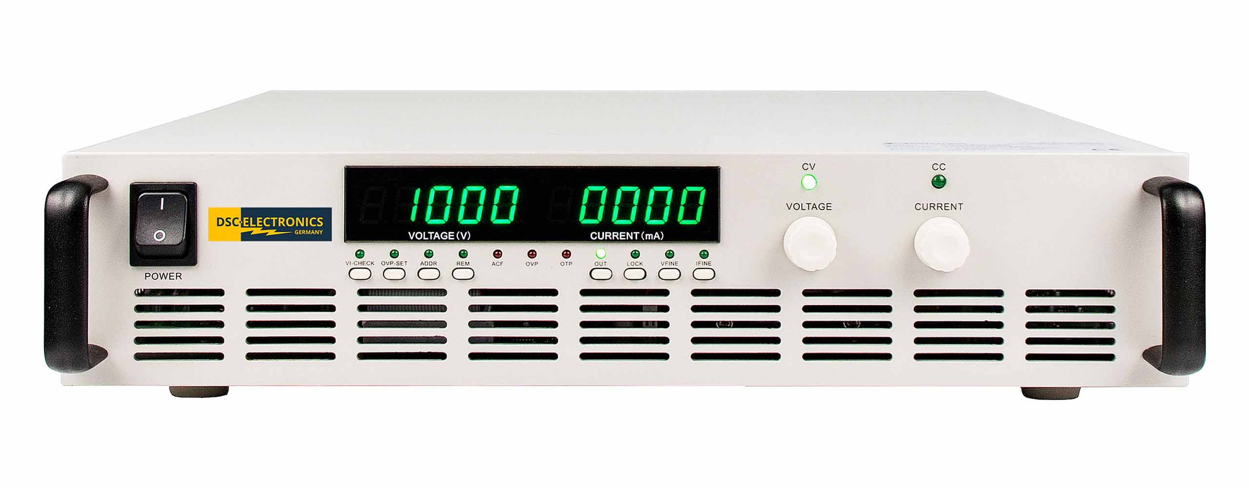
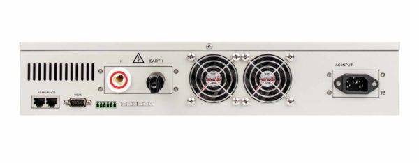
Digital Versatility for Your High-Voltage Application: The DP-PH series from DSC-Electronics Germany offers CC/CV control, RS232/RS422/RS485 with Modbus RTU, and optional LAN or analog I/O instead of RS232. Interlock is standard; master/slave is available upon request for full-width models. Expandable with AP9, AP7, and AP5; no remote measurement.
High voltage with the versatility of a digital laboratory power supply: The DP-PH Series combines the familiar operation and flexible interfaces of the DP-P Series with output ranges for higher voltages and lower currents. This provides you with a suitable foundation for high-voltage testing, development tasks, and automated laboratory applications, without sacrificing ease of setup and data acquisition.
Operate the unit directly from the front panel or integrate the power supply into your test bench. RS232, RS422, and RS485 support Modbus RTU; optional features include LAN with server/client operation or analog I/O for 0 … 5 V, 0 … 10 V, or 4 … 20 mA. In this case, analog I/O replaces RS232. The digital control loop continuously monitors voltage and current and enables automatic switching between constant-voltage and constant-current (CV/CC) operation.
| Connectivity | RS232, RS422, and RS485 with Modbus RTU. Optional LAN or analog I/O; analog I/O replaces RS232. Interlock loop and status output are standard. |
| Functionality | CC/CV operation within the model-specific setting ranges. Software-based adjustment and recording. No remote measurement. |
| Output configuration | Up to and including 1500 V, potential-free as standard; above that, grounded. Short-circuit-proof output. Master/slave parallel operation available upon request only for full-width models, not for -S models. |
| Safety | Protection against overtemperature, overvoltage, and overcurrent with a status indicator. Lockable front-panel controls and a standard interlock loop. |
| extensibility | Compatible with AP9, AP7, and AP5. AP6 and AP8 are not compatible with the DP-PH series. |
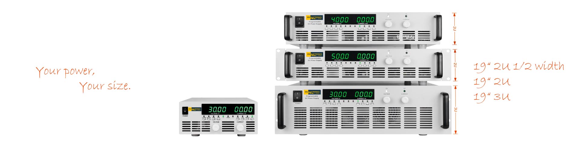
Illustrative image of the DP-PH series. The dimensions of the selected model apply for installation planning.
From compact half-width units to high-performance full-width models, the DP-PH series offers a variety of chassis sizes to suit your setup. The temperature-dependent fan control adjusts cooling based on the load. Full-width units can be mounted using the included rack brackets or used as freestanding units; a shared slot for two half-width units is available separately.
| The five listed 600W models up to and including 3 kV with the suffix -S | 19-inch half-width, 2U; 21.3 cm wide, 8.8 cm high, 34 cm deep |
| Other standard models up to and including 4 kW | 19-inch full-width, 2U; depth varies by model |
| Standard models over 4 kW | 19-inch full-width, 3U; depth varies by model |
Half-width devices can be identified by the suffix -S and do not support master/slave parallel operation. For special versions and specific model dimensions, the confirmed technical specifications apply.
Select the appropriate output range
For high-voltage models, the lower limit of the voltage adjustment range may be greater than 0 V. The model list shows the actual adjustable range. Models up to and including 1500 V are potential-free by default; higher-voltage versions have a grounded output with the specified polarity. Remote measurement is not supported by the DP-PH series.
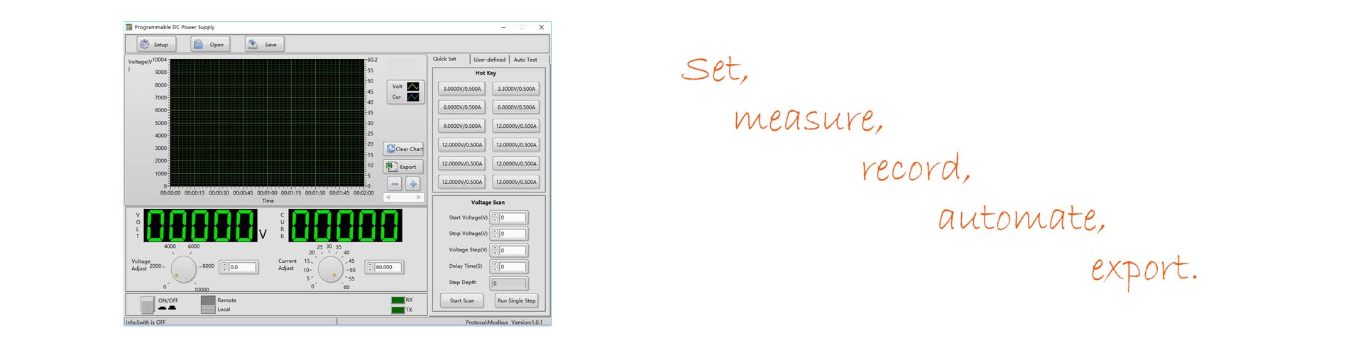
Illustration of the software used to configure, monitor, and program the output values.
Recurring voltage and current waveforms can be programmed, executed, and recorded using the software suite. Use the digital interfaces or the optional LAN connection to integrate the device into your test process. The documented Modbus RTU protocol for the serial interfaces also simplifies the development of custom control systems and integration into LabVIEW applications. Direct operation via the front panel remains possible regardless.
Expand your high-voltage power supply with features tailored to your load and test procedure. The AP9, AP7, and AP5 modules, which are custom-built, are available for the DP-PH series. The AP6 and AP8 are not compatible.
Integrated reverse current protection and additional protection modules
The output rectifier stage already provides basic protection against same-polarity reverse currents within the device’s permissible limits. For high-energy loads or reverse voltage transients, this protection can be specifically supplemented. The power supply is not an energy sink with unlimited capacity; reverse current, reverse voltage, and stored load energy determine the required design.
Model AP9: Application-Specific Reverse Current and Reverse Voltage Protection
With the AP9, you can tailor the additional protection to demanding inductive or capacitive loads. The module is custom-manufactured to order for the expected currents, voltages, and energy levels. Options include a combined protection circuit against high reverse currents and reverse voltages—particularly reverse-polarity transients—or a design as an active braking chopper to convert regenerated energy into heat. The specifications and permissible duty cycles will be agreed upon to suit your test setup.
Model AP7: Additional input-side EMC filter
When there are increased requirements on the mains side, the AP7 supplements the existing filtering with a three-stage EMC filter. This helps reduce conducted interference in demanding test and production environments. The single- or three-phase configuration and current-carrying capacity are selected to match the power supply unit.
Model AP5: Mechanical Isolation of the Load
Supplement the electronic output control with a physical isolation point between the power supply and the load or test bench. The AP5 is manufactured to match the voltage, current, and application, and is integrated into your system’s safety concept.
All AP modules are manufactured to order. The cabinet , and electrical specifications are tailored to your application.
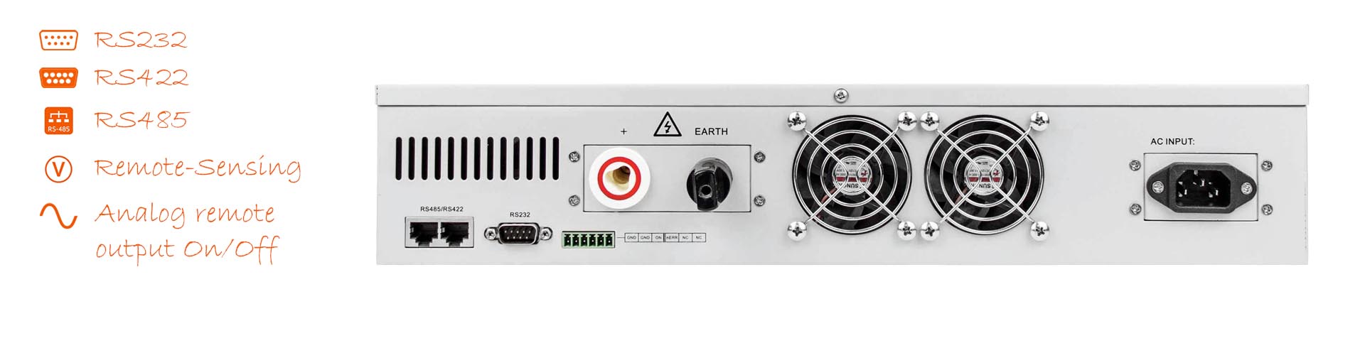
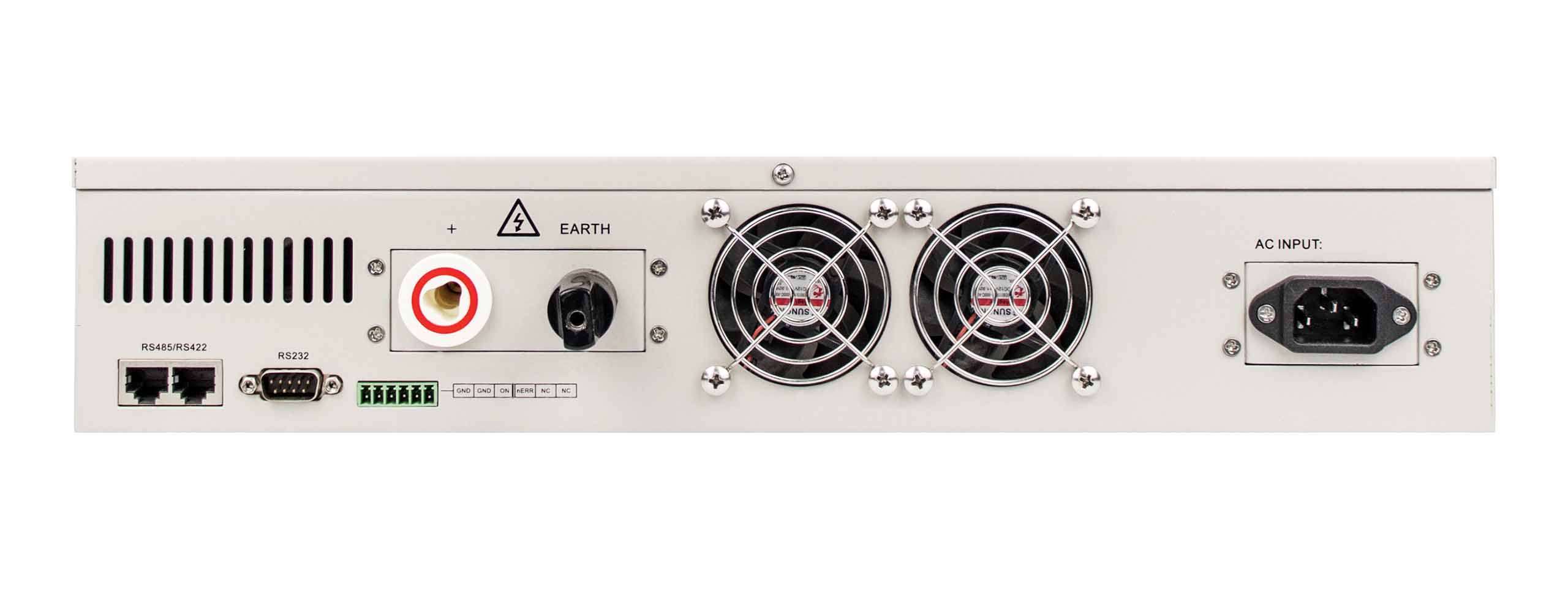
Illustration of a DP-PH model with a grounded output. Pin assignments and cabinet vary by model and configuration.
Digital interfaces (standard)
, RS232, RS422, and RS485 with Modbus RTU enable the configuration and monitoring of output values. If analog I/O is selected, RS232 is not available.
LAN (optional)
Integrate the power supply into your network infrastructure. The LAN interface can be configured for server or client operation, depending on your application.
Analog I/O (optional)
Inputs and outputs for 0 … 5 V, 0 … 10 V, or 4 … 20 mA are available for direct connection to analog controllers. The signal standard and configuration are specified at the time of ordering. The analog interface replaces RS232.
Interlock Loop (Standard)
The 5V loop blocks the output when the loop is open and enables it when the loop is closed. Upon request, it can be configured at the factory as an external output ON/OFF trigger. The user cannot switch between these two functions after installation.
Status Output (Standard)
The separate status output indicates the device status using 0 V for errors and 5 V for normal operation. It supplements the monitoring of your application independently of any optional analog actual value outputs.
Master/Slave Parallel Operation (optional)
Full-width devices ordered with this option can be operated in a master/slave configuration. The half-width versions with the suffix -S do not support this function. For bipolar configurations with a grounded center point, a suitable output configuration is required.
| Weight | 20 kg |
|---|---|
| Dimensions | 8.8 H cm x 48.2 W cm x 53.3 D cm |
| Manufacturer | DSC-Electronics Germany |
| Series | DP-PH Series |
| Input voltage | 360 … 420VAC 3 phases |
| Input frequency | 47 ... 63Hz |
| Efficiency (100% load) | 85% |
| Output type | Variable DC |
| Output configuration | Positive, earthed, Negative, earthed |
| Output voltage | 200V ... 3kV |
| Output current | 0 ... 1.3A |
| Power | 0 ... 4kW |
| Load regulation U | ≤0.5% + 2 LSB |
| Load regulation I | ≤0.5% + 2 LSB |
| Line regulation U | ≤0.1% + 2 LSB |
| Line regulation I | ≤0.1% + 2 LSB |
| Display resolution U | 1V |
| Display resolution I | 1mA |
| Display accuracy U | ≤0.2% ± 2 LSB |
| Display accuracy I | ≤0.5% ± 2 LSB |
| Setting resolution U | 1V |
| Setting resolution I | 1mA |
| Setting accuracy U | ±0.2% ± 2 LSB |
| Setting accuracy I | ±0.5% ± 2 LSB |
| Residual ripple U | ≤0.1%FS |
| Residual ripple I | ≤0.1%FS |
| Command response time | 50ms |
| Functionality | CC - Constant Current Mode, CV - Constant Voltage Mode |
| Reverse current protection | Integrated, passive (same-polarity return currents) |
| Telemetering compensation | No |
| Parallel connection | Yes |
| Series connection | No |
| Digital communication | LAN, RS232, RS422, RS485 |
| Communication protocol | Modbus RTU |
| Feedback output I | 0 ... 5V signal, 0 ... 10V signal, 4 ... 20mA signal |
| Feedback output P | No |
| Feedback output U | 0 ... 5V signal, 0 ... 10V signal, 4 ... 20mA signal |
| External control signal I | 0 ... 5V signal, 0 ... 10V signal, 4 ... 20mA signal |
| External control signal P | No |
| External control signal U | 0 ... 5V signal, 0 ... 10V signal, 4 ... 20mA signal |
| Ext. output interlock | Closed/Open Loop |
| Certification | CE, ROHS |