


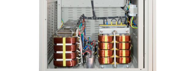

High-Frequency AC Power Supply 0 ... 300Vrms 0 ... 260A 90kVA - DF-CM6390
The DF-CM6390 combines three-phase 0–300 V RMS L-N with a total rated apparent power of 90 kVA. The output frequency is adjustable from 350 to 450 Hz as standard. The sine wave output is potential-free.
Digitally controlled sinusoidal AC voltage for testing applications at higher frequencies. As an alternative to the standard range of 350 … 450 Hz, a version for 200 … 2500 Hz is available. Designed for 24/7 operation even at the highest specified frequency, with optional digital or analog interfaces and a potential-free output as standard.
-
Power supply units (voltage / current sources) (617)
The DF-CM6390 delivers a total of 90 kVA at three-phase 0–300 V RMS L-N and 350–450 Hz as standard. This configuration is suitable for larger 400-Hz test benches with multiple connected assemblies. This model is particularly well-suited , for example , for vehicle electrical system integration tests, high-power AC/DC input stages, and electrical aviation power units. Different supply conditions can be set without having to switch between fixed power sources.
The DF-CM series expands industrial AC test technology to include higher output frequencies. Digitally controlled sinusoidal AC voltage and optional remote control interfaces support development test benches and processes involving frequency-dependent loads.
As an alternative to the standard frequency range of 350 Hz … 450 Hz, a version for 200 Hz … 2,500 Hz can be selected when placing an order. Even at the highest frequency specified for the ordered version, the devices are designed for 24/7 continuous operation within their rated parameters and environmental conditions.
Your Benefits at a Glance
– Standard frequency range: 350 Hz … 450 Hz; 200 Hz … 2,500 Hz available upon request
– Sinusoidal single- or three-phase AC output
– Designed for continuous operation even at the highest specified frequency
– Potential-free output as standard; grounded version available upon request
– Standard LV ranges: 0 … 150 Vrms L-N and FS: 0 … 300 Vrms L-N
– Optional remote control via RS232, RS485, or analog I/O
– Command response time for digital control under 20 ms
– Recovery time ≤15 ms for a load change from 10% to 90%
Flexible testing, convenient operation
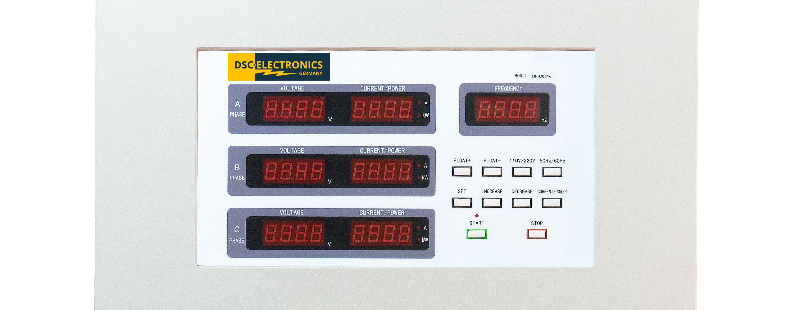
Set the voltage and frequency directly on the front panel, or control the power supply via your existing automation system. The digital control system continuously monitors the output values and operates in constant-voltage (CV) mode. The switchable LV/FS range offers you a higher output current at a lower voltage or an extended voltage range for specific test tasks.
Manufactured to meet your requirements
Voltage, current, apparent power, and frequency are selected to suit the application. The maximum values for the series also account for customer-specific devices and are not achievable simultaneously with every model. For continuous operation, the rated values as well as the ambient and cooling conditions of the ordered version apply.
Options: Your application determines the features
When placing your order, select the interfaces and initial configuration that match your test setup. This ensures you receive a power supply that integrates seamlessly into your existing infrastructure. The exact pin assignment can be found in the documentation for the model you ordered.
[U] External analog control U (optional)
Set the output voltage directly via your higher-level controller. Depending on the model, the optional input is available for 0 … 5 V, 0 … 10 V, or 4 … 20 mA.
[F] External analog feedback U (optional)
Monitor the actual voltage value in your control system or data acquisition system. Models are available with 0 … 5 V, 0 … 10 V, or 4 … 20 mA.
[G] External Analog Feedback I (optional)
The actual current value can also be output analog. The feedback output is available in 0 … 5V, 0 … 10V, or 4 … 20mA to suit your system.
[A] Interlock loop or external output control (optional)
Incorporate the output enable into your test sequence: The interlock loop blocks the output when the loop is open and enables it when the loop is closed. Alternatively, a version with external output control can be ordered. This function is set at the factory and cannot be changed by the user later.
[D] Digital Interface (optional)
, RS232, or RS485 make it easier to set and read device parameters in automated test benches. Both interfaces are configured with Modbus RTU by default. Alternatively, a simplified, documented proprietary protocol is available upon request. The desired protocol must be specified at the time of ordering, as a later change would require replacement of the control board. RS422 is not offered.
[O] Output Configuration
The AC output is potential-free by default. Available options include the potential-free version without its own residual current circuit breaker (O6), the potential-free version with an integrated residual current circuit breaker (O7), and a grounded version available upon request. This allows the power supply to be tailored to the grounding and protection concept of your application. The protective grounding of the housing must be considered separately. Details are provided in the manual and the functional and wiring diagram.
| Weight | 730 kg |
|---|---|
| Dimensions | 130 H cm x 75 W cm x 138 D cm |
| Manufacturer | DSC-Electronics Germany |
| Series | DF-CM Series |
| Input voltage | 360 … 420 VAC, 3-phase |
| Input frequency | 47 ... 63Hz |
| Efficiency (100% load) | 85% |
| Output type | Variable AC true sine 3 phases |
| Output configuration | Earthed, floating, floating with own residual current circuit breaker |
| Output voltage | 0 ... 300Vrms L-N |
| Output current 0 ... 150Vrms L-N | 0 ... 260A |
| Output current 0 ... 300Vrms L-N | 0 ... 130A |
| Output frequency | 350Hz ... 450Hz |
| Power | 0 ... 90kVA |
| Load regulation U | ≤1% |
| Line regulation U | ≤1% |
| Display resolution U | 100mV |
| Display resolution I | 100mA |
| Display resolution F | 0.01Hz |
| Display resolution P | 0.01kW |
| Display resolution PF | 0.01 |
| Display accuracy U | ±1% FS |
| Display accuracy I | ≤0.5% rdg + (±0.2% FS) |
| Display accuracy F | ≤0.5% of reading |
| Display accuracy P | ≤0.5% rdg + (±0.2% FS) |
| Setting resolution U | 100mV |
| Setting resolution F | 0.01Hz |
| Setting accuracy U | ±1% FS |
| Setting accuracy F | ±0.1% FS |
| Harmonic distortion | ≤2% |
| Crown Factor Deviation | ≤2% |
| Voltage stability | ±1% |
| Frequency stability | ≤0.1% FS |
| Command response time | 20ms |
| Functionality | CV - Constant Voltage Mode |
| Parallel connection | No |
| Series connection | No |
| Digital communication | RS232, RS485 |
| Communication protocol | Proprietary open protocol, Modbus RTU |
| Feedback output I | 0 ... 5V signal, 0 ... 10V signal, 4 ... 20mA signal |
| Feedback output P | No |
| Feedback output U | 0 ... 5V signal, 0 ... 10V signal, 4 ... 20mA signal |
| External control signal I | No |
| External control signal P | No |
| External control signal U | 0 ... 5V signal, 0 ... 10V signal, 4 ... 20mA signal |
| Ext. output interlock | Closed/Open Loop |
| Certification | CE, ROHS |